Assistance device for transient acceleration and deceleration phases

A technology for turbine engines and generators, which is applied to the ignition of jet propulsion devices, gas turbine devices, turbine/propulsion devices, etc., can solve problems such as the limitation of surge margins in the acceleration performance of turbine engines, and achieve the goal of reducing speed and size Effect

Active Publication Date: 2010-02-17
TURBOMECA SA
View PDF0 Cites 17 Cited by
  • Summary
  • Abstract
  • Description
  • Claims
  • Application Information

AI Technical Summary

Problems solved by technology

[0012] Therefore, it can be understood that the acceleration performance of such a turbine engine is limited by the surge margin

Method used


Image

  • Assistance device for transient acceleration and deceleration phases
  • Assistance device for transient acceleration and deceleration phases
  • Assistance device for transient acceleration and deceleration phases

Examples


Embodiment Construction

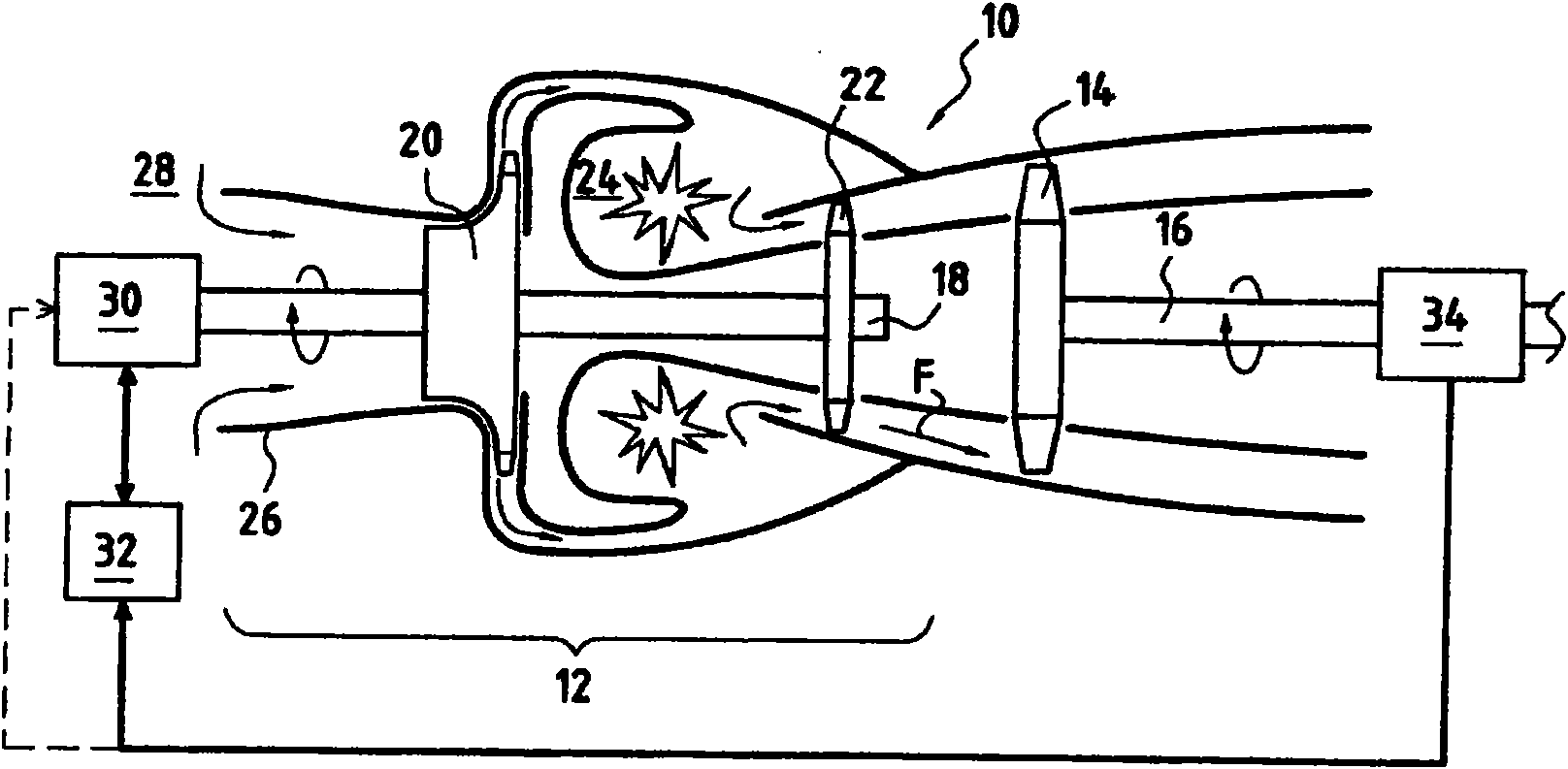
[0055] figure 1 is a view showing a turbine engine 10 constituting a first embodiment of the present invention and used in particular to drive a helicopter rotor (not shown) in rotation, the turbine engine 10 including a gas generator 12 and a free turbine 14 capable of receiving gas The air flow F generated by the generator 12 is driven to rotate.

[0056] The free turbine 14 is mounted on a shaft 16 which transmits the rotational motion to a receiving unit, for example the main rotor of a helicopter.

[0057] like figure 1 The illustrated turbine engine 10 is of the rear output type. Turbine engines with a front-exit free turbine shifted by an external shaft or with a front-exit free turbine shifted by a coaxial shaft are conceivable without departing from the scope of the invention.

[0058] The gas generator comprises a rotating shaft 18 on which a centrifugal compressor 20, a turbine 22 are mounted and axially arranged between the compressor 20 and the turbine 22 when th...


PUM


Abstract

The invention relates to a turboshaft engine (10) in particular for a helicopter, that comprises a gas generator (12) and a free turbine (14) rotatingly driven by the gas flow (F) generated by the gas generator (12). The invention is characterised in that the turboshaft engine (10) further includes a motor / generator coupled (30) to a shaft (18) of the gas generator (12) for providing an amount ofadditional rotational kinetic energy to the shaft (18) during an acceleration phase of the turboshaft engine (10) or for diverting an amount of rotational kinetic energy from the shaft (18) during a deceleration phase of the turboshaft engine.

Description

technical field [0001] The invention relates to the field of gas turbines, in particular the invention relates to turbine engines for aircraft such as helicopters. [0002] More specifically, the present invention relates to a turbine engine, in particular for helicopters, comprising a gas generator and a free turbine driven in rotation by the flow generated by the gas generator. Background technique [0003] Traditionally, gas generators include at least one centrifugal compressor and turbine coupled together for rotation. The operation is as follows: the cooling air entering the turbine engine is compressed by the rotation of the compressor before being sent into the combustion chamber where it is mixed with fuel. Then, the combustion gas in the combustion chamber is discharged to the turbine of the gas generator at high speed. [0004] Then, a first expansion takes place in the turbine of the gas generator, during which said turbine extracts the energy required to drive...

Claims


Application Information

Patent Timeline
Patent Type & Authority Applications(China)
IPC IPC(8): F01D15/10F02C7/26
CPCF05B2260/85F01D15/08F05B2260/903F01D15/10F05D2260/85F05B2220/309F05D2260/903F05D2220/329F02C7/26F02C7/32F02C3/10F05B2260/90F05D2260/90
Inventor 埃德格·海纳尔热拉尔德·森格尔
Owner TURBOMECA SA
Why Eureka
Try Eureka