
Energy-saving sliding door and window

A technology of sliding doors and windows and sliding windows, which is applied in the field of doors and windows of industrial and civil buildings, can solve problems such as infiltration, and achieve the effects of simplified manufacturing process, outstanding sound insulation, heat insulation and energy saving, and reasonable design

Inactive Publication Date: 2010-02-24
杭州新域郡邦建筑材料有限公司
View PDF0 Cites 11 Cited by
  • Summary
  • Abstract
  • Description
  • Claims
  • Application Information

AI Technical Summary

Problems solved by technology

The disadvantage of this type of sliding window is that the lower window frame is mostly horizontal. When the rainwater flows down from the surface of the glass window and is not discharged in time, it will seep into the house from below the window.

Method used


Image

  • Energy-saving sliding door and window
  • Energy-saving sliding door and window
  • Energy-saving sliding door and window

Examples


Embodiment 1

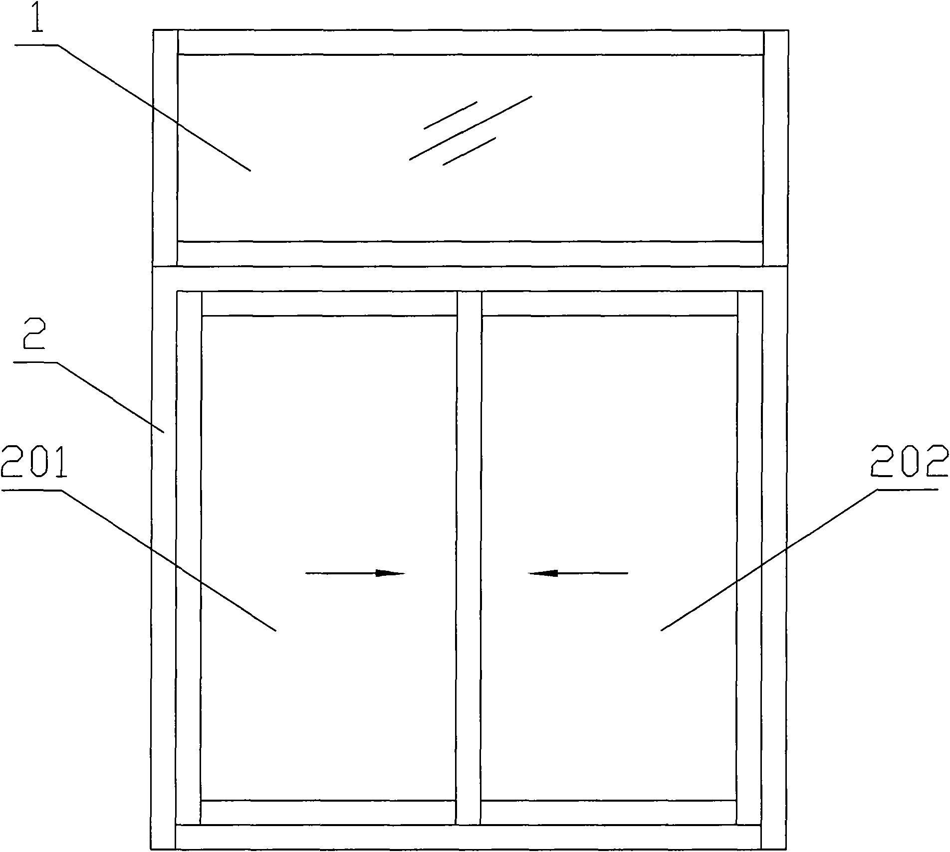
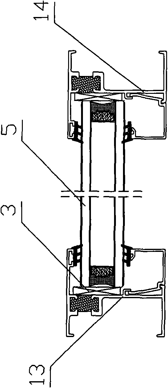
[0027] An energy-saving sliding door and window, such as Figure 1 to Figure 4 As shown, it includes an upper bright part 1 and a push-pull part 2 connected under the upper bright part 1. The upper bright part 1 includes an upper frame 11 and a lower frame 12 facing each other and is vertically and fixedly connected with the upper frame 11 and the lower frame 12. The left frame 13 and the right frame 14, the upper frame 11, the lower frame 12, the left frame 13 and the right frame 14 form the outer frame of the bright part 1, and the glass 5 is inlaid in the outer frame; the push-pull part 2 includes opposite upper rails Frame 21, lower track frame 22 and left seal 23 and right seal 24 which are vertical and fixedly connected with upper track frame 21 and lower track frame 22, upper track frame 21, lower track frame 22, left seal 23 and right seal 24 form a push-pull part 2 The outer frame of the upper bright part 1 and the upper rail frame 21 of the push-pull part 2 are provi...

Embodiment 2

[0038] The biggest difference between Embodiment 2 and Embodiment 1 is that the lower lighting part is connected under the push-pull part, that is, the upper bright part originally arranged above the push-pull part is replaced with the lower bright part arranged below the push-pull part.

Embodiment 3

[0040] The biggest difference between Embodiment 3 and Embodiment 1 is that the side of the push-pull part is connected to the side-light part, that is, the upper-light part originally arranged above the push-pull part is replaced with a side-light part arranged on the side of the push-pull part. The height of the push-pull part is consistent with the height of the side light part.


PUM


Abstract

The invention relates to the field of doors and windows of industrial and civil buildings, discloses an energy-saving sliding door window. The sliding door window comprises an upper transparent part and a sliding part connected below the upper transparent part, wherein a heat-insulating spliced pipe is arranged between a lower frame of the upper transparent part and an upper rail frame of the sliding part, and the lower end of the spliced pipe is connected with heat-insulating hard rubber. Frames of the upper transparent part are spliced at angles of 90 degrees and fastened and fixed by screws. The invention has reasonable integral structure design, grand and graceful style and graceful and smooth appearance. Various plastic pieces, rubber strips, and the like and hollow glass panels are matched so as to ensure that the effects of heat and sound insulation, energy saving and decoration of the whole window are outstanding, thus the window has the characteristics of high air tightness, high water tightness, high safety, good drainage effect, high precision, and the like and is a preferred type of various buildings such as luxurious buildings, office buildings, high-rise buildings, public buildings, and the like.

Description

technical field [0001] The invention relates to the field of doors and windows of industrial and civil buildings, in particular to an energy-saving sliding door and window. Background technique [0002] At present, my country's energy consumption and waste are becoming more and more serious, especially in the northern alpine regions where heating in winter and air conditioning and cooling in southern summer consume a lot of energy. Therefore, it is imperative to vigorously promote energy-saving and environmental protection technologies for building construction. According to the statistics of relevant departments, the total energy consumption of doors and windows accounts for more than half of the total energy consumption of buildings. Therefore, it is very important to choose high-quality thermal insulation and energy-saving doors and windows in housing construction. [0003] Sliding doors and windows save space when opened, have good ventilation effects and avoid the short...

Claims


Application Information

Patent Timeline
IPC IPC(8): E06B3/46E06B7/22E06B7/16E06B3/12E06B3/263E06B3/66E06B9/52E06B7/26
Inventor 王郁
Owner 杭州新域郡邦建筑材料有限公司
Learn More