Hydraulic power source system

A hydraulic power source and hydraulic system technology, applied in the direction of fluid pressure actuators, etc., can solve the problems of large volume, weight, restriction, and difficult use and operation, and achieve the effects of reducing production costs and improving reliability and safety

Active Publication Date: 2010-02-24
CHENGDU CHENGSHE AVIATION TECH
0 Cites 10 Cited by

AI-Extracted Technical Summary

Problems solved by technology

If the flow rate of the system is large, the volume and weight of the switching device need to be large in order to meet the ...

Method used

Fuel tank 10, low-pressure oil delivery pump group 11 are connected with external refueling check valve 13, the 3rd oil filter 14 and refueling switch 17 successively, between the 3rd oil filter 14 and fuel tank 10, insert refueling pressure 15 switches, by adjusting Refueling pressure switch 15 can realize external refueling ...

Abstract

The invention discloses a hydraulic power source system which comprises a hydraulic system and an auxiliary hydraulic device. The hydraulic system comprises an oil pump, a one-way valve, a first oil filter, a second oil filter, a switch, a scavenge filter and a radiator which are sequentially connected to form a loop; the auxiliary hydraulic device comprises an oil tank and a low-pressure oil transfer pump unit; the oil tank is connected between the oil pump and the radiator of the hydraulic system by a one-way counterbalance valve; and the low-pressure oil transfer pump unit is connected between the first oil filter and the one-way valve of the hydraulic system by an oil supply one-way valve. The invention has the advantages that a switching device in an open-close mode in a common hydraulic power source system is canceled and replaced by a hydraulic auxiliary system, thereby improving the reliability and the safety of the hydraulic power source system and decreasing the production cost. When the hydraulic system works, the auxiliary hydraulic device does not work, and the common characteristics and respective independence of the two systems are fully ensured.

Application Domain

Technology Topic

Image

  • Hydraulic power source system
  • Hydraulic power source system

Examples

  • Experimental program(1)

Example Embodiment

[0016] All features disclosed in this specification, or steps in all methods or processes disclosed, may be combined in any manner, except for mutually exclusive features and/or steps.
[0017] Any feature disclosed in this specification (including any appended claims, abstract and drawings), unless expressly stated otherwise, may be replaced by alternative features which are equivalent or serve a similar purpose. That is, unless expressly stated otherwise, each feature is one example only of a series of equivalent or similar features.
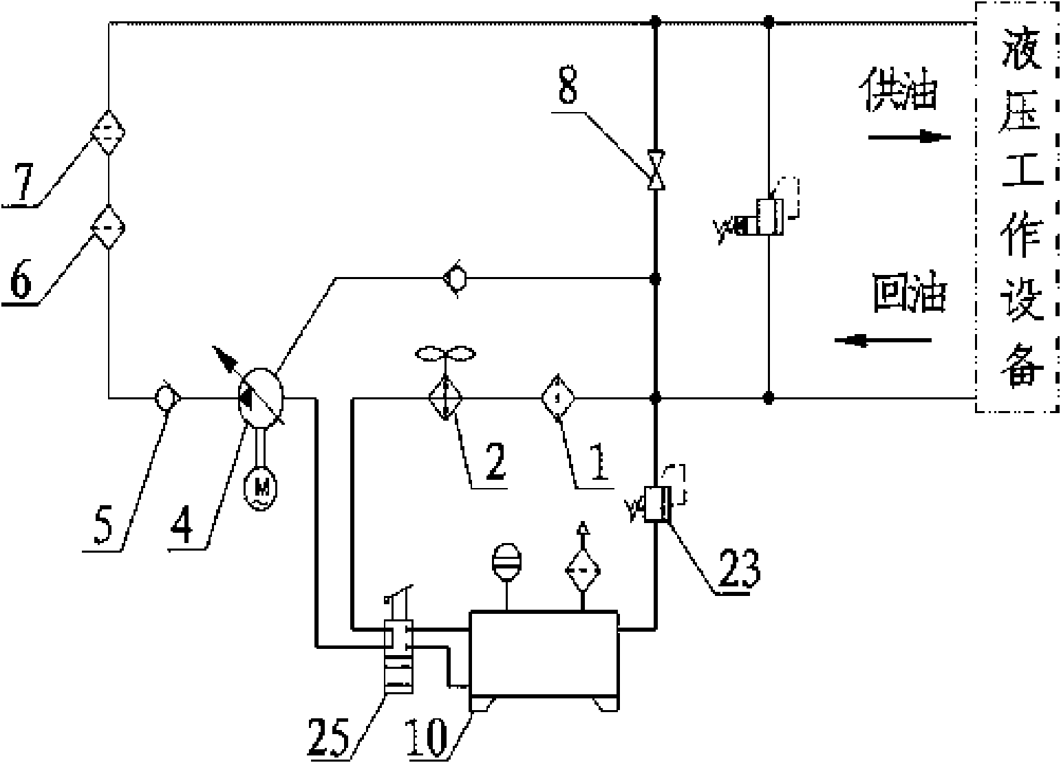
[0018] like figure 1 As shown, a hydraulic power source system includes a hydraulic system and an auxiliary hydraulic device. The hydraulic system includes an oil pump 4, a check valve 5, a first oil filter 6, a second oil filter 7, a switch 8, an oil return filter 1 and a cooling The circuit formed by the device 2; the auxiliary hydraulic device includes a fuel tank 10 and a low-pressure oil delivery pump group 11, the fuel tank 10 is connected between the oil pump 4 and the radiator 2 of the hydraulic system through the one-way back pressure valve 3, and the low-pressure oil delivery pump group 11 is connected through the oil supply unit The directional valve 12 is connected between the first oil filter 6 and the one-way valve 5 of the hydraulic system.
[0019] The oil tank 10, the low-pressure oil delivery pump group 11 are connected to the external refueling check valve 13, the third oil filter 14 and the refueling switch 17 in sequence, and the refueling pressure switch 15 is connected between the third oil filter 14 and the fuel tank 10. By adjusting the refueling pressure switch 15. External refueling can be better realized. An overflow valve 16 can also be connected between the third oil filter 14 and the oil tank 10, and connected in parallel with the refueling pressure switch 15, so that when the refueling pressure switch 15 is not opened, the oil can be returned through the overflow valve 16 to protect the external refueling pipeline .
[0020] The working principle of the present invention is: when the auxiliary hydraulic device is working, the low-pressure oil delivery pump group 11 is working, the refueling switch 17 is turned off, the oil liquid opens the oil supply check valve 12 and enters the hydraulic system, and passes through the first oil filter 6 and the second oil filter 7 Filtration, through the opened switch 8, oil return filter 1 and radiator 2, the one-way back pressure valve 3 is opened by pressure, and returns to the oil tank 10 to form a circulating filter to replenish the oil in the hydraulic system. If an external hydraulic power unit is connected, the external hydraulic power unit can be supplied with oil.
[0021] After a certain cycle, the fuel tank oil and the pipeline are well filtered, and the external refueling check valve 13, the third oil filter 14, the refueling pressure switch 15, and the refueling switch 17 can be used for external refueling.
[0022] When the hydraulic system is working, the auxiliary hydraulic device has stopped working. Due to the oil supply check valve 12, the oil supply during work cannot be returned to the auxiliary hydraulic system; and because the opening pressure set by the one-way back pressure valve 3 is greater than the maximum oil return pressure, the one-way back pressure valve 3 is completely closed, so It ensures that the oil tank 10 does not participate in the work and forms a complete closed system. When an unexpected situation occurs and the pressure of the closed system is too large and exceeds the opening pressure of the one-way back-pressure valve 3, the one-way back-pressure valve 3 can also play a role in recovery. The role of the oil relief valve.
[0023] The present invention is not limited to the foregoing specific embodiments. The present invention extends to any new feature or any new combination disclosed in this specification, and any new method or process step or any new combination disclosed.

PUM

no PUM

Description & Claims & Application Information

We can also present the details of the Description, Claims and Application information to help users get a comprehensive understanding of the technical details of the patent, such as background art, summary of invention, brief description of drawings, description of embodiments, and other original content. On the other hand, users can also determine the specific scope of protection of the technology through the list of claims; as well as understand the changes in the life cycle of the technology with the presentation of the patent timeline. Login to view more.

Similar technology patents

Hacking defending implementation method and device

Owner:MICRO DREAM TECHTRONIC NETWORK TECH CHINACO

Cheating prevention electronic weighing apparatus calibrating system and method

Owner:CHENGDU JIUZHOU ELECTRONIC INFORMATION SYSTEM CO LTD

Classification and recommendation of technical efficacy words

  • Reduce manufacturing cost
  • Improve safety and reliability

Electric power supply device with electric shock protection function

Owner:国网安徽省电力有限公司铜陵市义安区供电公司
Why Eureka
Try Eureka