Micro-electrical conductor solder terminal

A technology for welding terminals and conductors, which is applied in the direction of welding/fusion connection, etc. It can solve the problems of unreal welding, undetectable, melting and fracture of small conductors, etc., and achieve the effect of high welding quality and improved efficiency

Inactive Publication Date: 2010-02-24
于国强
View PDF0 Cites 0 Cited by
  • Summary
  • Abstract
  • Description
  • Claims
  • Application Information

AI Technical Summary

Problems solved by technology

The problems that cannot be solved by the existing technology are: one is virtual welding, that is, the welding time is slightly shorter, or the heat generated by the welding current is slightly smaller, which leads to false welding, and the other is over-welding, that is, the welding time is too short. If it is slightly longer, or the welding current and heat generation are slightly higher, the tiny conductors being welded will melt and fracture
The phenomenon of virtual welding or over welding cannot be seen from the surface, and it is more troublesome to check.
It is difficult to detect with high-precision instruments, especially for mass-produced products.

Method used


Image

  • Micro-electrical conductor solder terminal
  • Micro-electrical conductor solder terminal
  • Micro-electrical conductor solder terminal

Examples


Embodiment 1

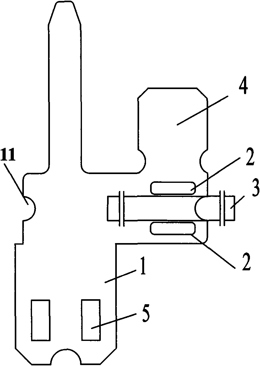
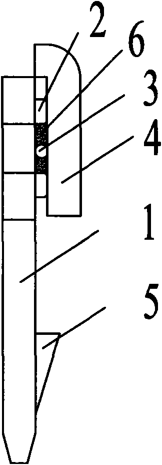
[0026] Such as figure 1 As shown, the welding plate part 1 of the terminal according to the present invention has two protrusions 2 on the welding plate part 1, and the conductor 3 to be welded is between the two protrusions. There is a bendable cover part 4, and the welded plate part 1 is also provided with a protruding buckle 5. Such as figure 2 As shown, after the welding process of the present invention, the conductor 3 is placed between the two protrusions 2 to clamp the filler 6 for welding, and the bendable cover plate part 4 can effectively protect the firmness of the welded part after being bent. The semicircular hole 11 on the edge of the welding plate part 1 is used as a welding positioning female hole. Of course, this hole can also be set as a circular or square hole or a semi-square hole as a welding positioning female hole, which can realize the positioning purpose of the present invention. .

Embodiment 2

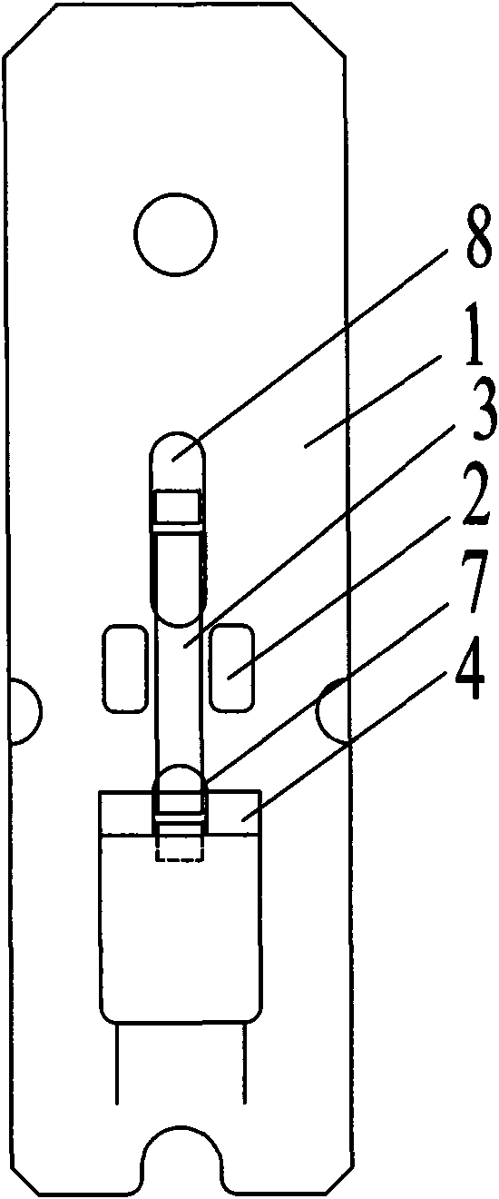
[0028] Such as image 3 As shown, the welding plate part 1 of the terminal according to the present invention has two protrusions 2 on the welding plate part 1, and the conductor 3 to be welded is between the two protrusions. There is a bendable cover plate part 4, and the bendable cover plate part 4 is provided with a through hole 7 for the conductor to pass through, and the welding plate part 1 is also provided with a circular racetrack-shaped through hole for the conductor to pass through 8 is used as a welding positioning female hole. Such as Figure 4 As shown, after the welding process of the present invention, the conductor 3 is placed between the two protrusions 2 to clamp the filler for welding, and after the bendable cover plate part 4 is bent (as shown by the dotted line in the figure), it can be effectively Protect the firmness of the welding part of the conductor 3 .

Embodiment 3

[0030] Such as Figure 5 As shown, the welding plate part 1 of the terminal according to the present invention is provided with three protrusions 2 on the welding plate part 1, which are used in pairs, and there are two channels in the middle. Body 3, thick conductor 9, the upper part of the protrusion 2 is provided with a bendable cover part 4, and the welding plate part 1 and the bendable cover part 4 are provided with a circular runway for the conductor to pass through The through-hole 7 is used as the welding positioning female hole, and a groove 10 matching the shape of the thick conductor 9 is provided between the two protrusions on the welding plate part 1 for welding the thick conductor 9, and the welding plate part 1 also has a A protruding block 5 is provided. Such as Figure 6 As shown, after the welding process of the present invention, the thin conductor 3 and the thick conductor 9 are placed between the two protrusions 2 to clamp the filler for welding, and aft...


PUM


Abstract

The invention discloses a micro-electrical conductor solder terminal, comprising a soldering flat part for holding a soldering electric conductor. The micro-electrical conductor solder terminal is characterized by further comprising a flexible cover plate part which is used for clamping the soldering electric conductor and is connected with the flat part, wherein the soldering flat part is provided with more than one bugles for limiting the interval between the flexible cover plate part and the soldering flat part. The micro-electrical conductor solder terminal of the invention greatly improves soldering efficiency, the key is that general soldering equipment capable of controlling pressure, time and current can be utilized if only in accordance with soldering requirements, the solder junctions after soldering are natural, plum, thick and solid; meanwhile, due to the protection of bugles on the electric conductor, the phenomena of insufficient solder and over soldering can not occur.

Description

technical field [0001] The invention relates to the field of high-current welding processing of microelectronic and electric devices, in particular to a micro-conductor welding terminal used in the process of switching the internal and external power circuits of the device. Background technique [0002] In the field of welding and processing of microelectronics and electrical devices, it is often necessary to transmit one or more circuits of electricity or other electrical signals to one or more channels of receiving areas. The traditional welding method is to use point-to-point welding between lines. Defects are divided into two types, one is purely manual, using lead and zinc high-temperature melting welding, the defect is that there are many and messy welding points, and the other is high-current touch welding between lines, and the welding defect is that the diameter is 0.01 to 0.3 The thin metal conductors between them are prone to false welding or over welding. In par...

Claims


Application Information

Patent Timeline
Patent Type & Authority Applications(China)
IPC IPC(8): H01R4/02
Inventor 于国强
Owner 于国强
Why Eureka
Try Eureka