Micro-electrical conductor solder terminal
A technology for welding terminals and conductors, applied in the direction of welding/welding connection, etc., can solve the problems of unrealistic welding, undetectable, difficult to detect, etc., and achieve the effect of high welding quality and improving efficiency
- Summary
- Abstract
- Description
- Claims
- Application Information
AI Technical Summary
Problems solved by technology
Method used
Image
Examples
Embodiment 1
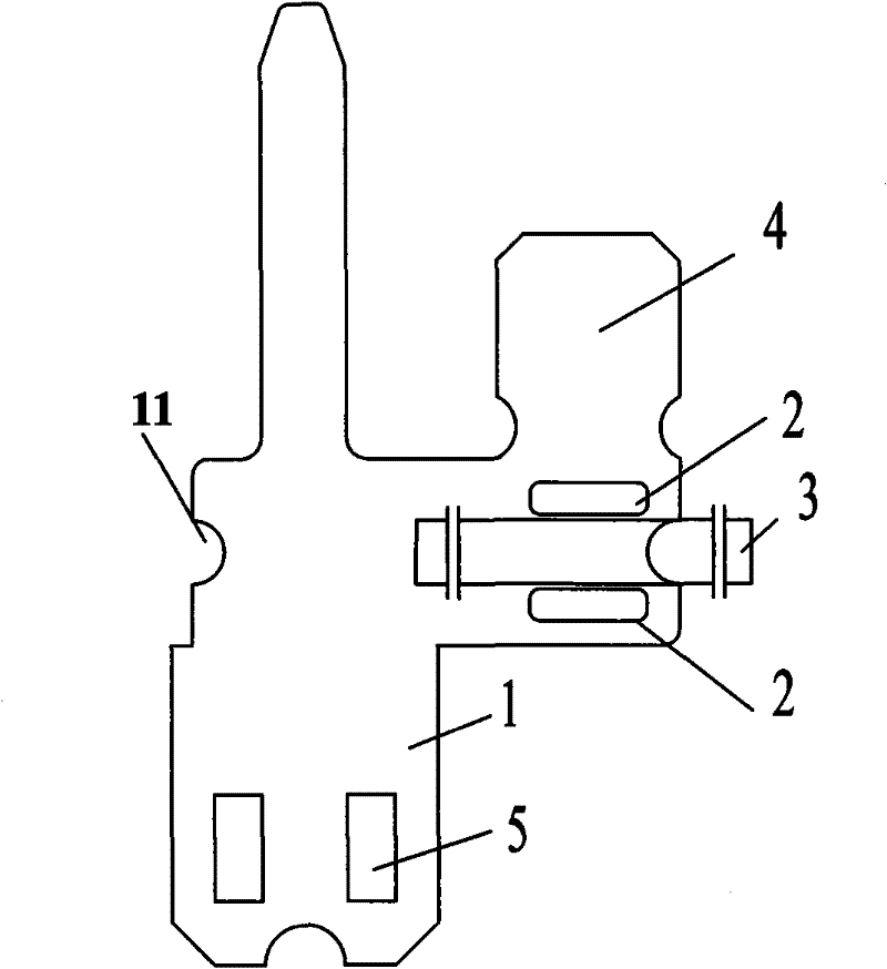
[0026] like figure 1 As shown, the welding plate part 1 of the terminal according to the present invention has two protrusions 2 on the welding plate part 1, and the conductor 3 to be welded is between the two protrusions. There is a bendable cover part 4, and the welded plate part 1 is also provided with a protruding buckle 5. like figure 2 As shown, after the welding process of the present invention, the conductor 3 is placed between the two protrusions 2 to clamp the filler 6 for welding, and the bendable cover plate part 4 can effectively protect the firmness of the welded part after being bent. The semicircular hole 11 on the edge of the welding plate part 1 is used as a welding positioning female hole. Of course, this hole can also be set as a circular or square hole or a semi-square hole as a welding positioning female hole, which can realize the positioning purpose of the present invention. .
Embodiment 2
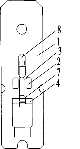
[0028] like image 3 As shown, the welding plate part 1 of the terminal according to the present invention has two protrusions 2 on the welding plate part 1, and the conductor 3 to be welded is between the two protrusions. There is a bendable cover plate part 4, and the bendable cover plate part 4 is provided with a through hole 7 for the conductor to pass through, and the welding plate part 1 is also provided with a circular racetrack-shaped through hole for the conductor to pass through 8 is used as a welding positioning female hole. like Figure 4 As shown, after the welding process of the present invention, the conductor 3 is placed between the two protrusions 2 to clamp the filler for welding, and after the bendable cover plate part 4 is bent (as shown by the dotted line in the figure), it can be effectively Protect the firmness of the welding part of the conductor 3 .
Embodiment 3
[0030] like Figure 5 As shown, the welding plate part 1 of the terminal according to the present invention is provided with three protrusions 2 on the welding plate part 1, which are used in pairs, and there are two channels in the middle. Body 3, thick conductor 9, the upper part of the protrusion 2 is provided with a bendable cover part 4, and the welding plate part 1 and the bendable cover part 4 are provided with a circular runway for the conductor to pass through The through-hole 7 is used as the welding positioning female hole, and a groove 10 matching the shape of the thick conductor 9 is provided between the two protrusions on the welding plate part 1 for welding the thick conductor 9, and the welding plate part 1 also has a A protruding block 5 is provided. like Figure 6 As shown, after the welding process of the present invention, the thin conductor 3 and the thick conductor 9 are placed between the two protrusions 2 to clamp the filler for welding, and after the...
PUM
 Abstract
Description
Claims
Application Information
 - R&D
- Intellectual Property
- Life Sciences
- Materials
- Tech Scout
- Unparalleled Data Quality
- Higher Quality Content
- 60% Fewer Hallucinations
Browse by: Latest US Patents, China's latest patents, Technical Efficacy Thesaurus, Application Domain, Technology Topic, Popular Technical Reports.
© 2025 PatSnap. All rights reserved.Legal|Privacy policy|Modern Slavery Act Transparency Statement|Sitemap|About US| Contact US: help@patsnap.com


