Shock absorber having a continuously variable valve with base line valving

A shock absorber, valve body technology, used in shock absorbers, springs/shock absorbers, shock absorbers, etc.

Active Publication Date: 2010-02-24
TENNECO AUTOMOTIVE OPERATING CO INC
View PDF0 Cites 17 Cited by
  • Summary
  • Abstract
  • Description
  • Claims
  • Application Information

AI Technical Summary

Problems solved by technology

An external control valve is fastened to the storage and intermediate pipes

Method used


Image

  • Shock absorber having a continuously variable valve with base line valving
  • Shock absorber having a continuously variable valve with base line valving
  • Shock absorber having a continuously variable valve with base line valving

Examples


Embodiment Construction

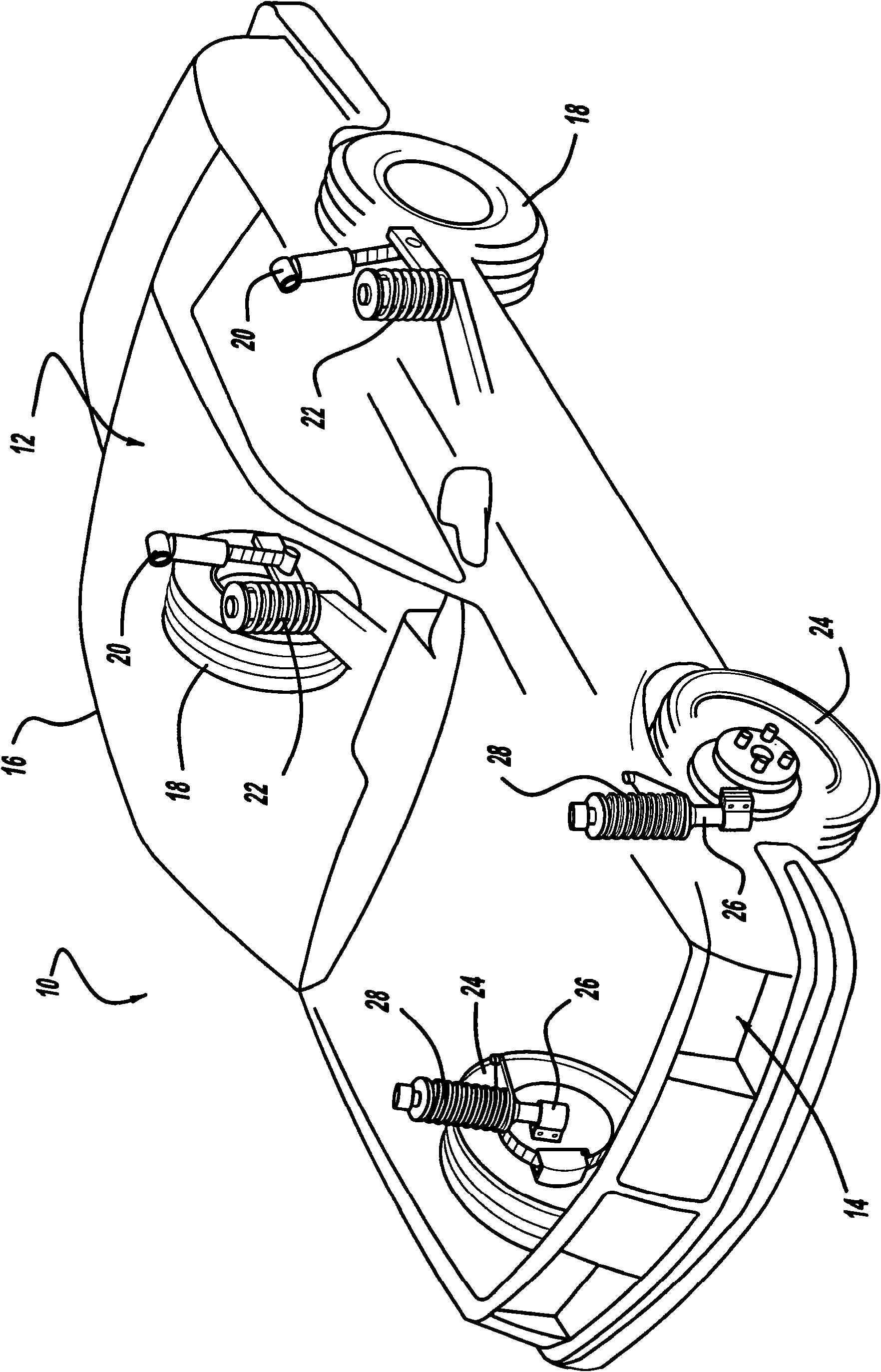
[0014] The following description is merely exemplary in nature, and is not intended to limit the disclosure, application, or uses. Referring now to the drawings in which like reference numerals designate like parts in several of the drawings, in figure 1 A vehicle comprising a suspension system with a shock absorber according to the present disclosure is shown in FIG. 2 , designated by reference numeral 10 .

[0015] The vehicle 10 includes a rear suspension 12 , a front suspension 14 and a body 16 . Rear suspension 12 has a laterally extending rear axle assembly (not shown) adapted to effectively support a pair of rear wheels 18 . The rear axle is attached to the vehicle body 16 by a pair of shock absorbers 20 and a pair of springs 22 . Similarly, the front suspension 14 includes a transversely extending front axle assembly (not shown) operatively supporting a pair of front wheels 24 . The front axle assembly is attached to the vehicle body 16 by a pair of shock absorbers ...


PUM


Abstract

A shock absorber includes an external control valve which controls the damping characteristics of the shock absorber. The external control valve controls the flow of fluid between the lower working chamber of the shock absorber and the reservoir chamber and between the upper working chamber of the shock absorber. The damping characteristics are dependent on the amount of current being applied to a solenoid valve which controls a fluid valve assembly. A soft fluid valve assembly is disposed in series with the fluid valve assembly to allow for the tuning of the damping forces at low current levels provided to the solenoid valve.

Description

technical field [0001] The present disclosure relates to hydraulic dampers or shock absorbers suitable for use in suspension systems, such as suspension systems for motor vehicles. More specifically, the present disclosure relates to hydraulic dampers or shock absorbers with externally mounted solenoid control valves with soft valves that produce different pressure flow characteristics as a function of the current supplied to the solenoid control valve. Valve (softvalving). Background technique [0002] The statements in this section merely provide background information related to the present disclosure and may not constitute prior art. [0003] A conventional hydraulic damper or shock absorber includes a hydraulic cylinder with one end adapted to attach to a sprung or unsprung mass of the vehicle. A piston is slidably disposed within the hydraulic cylinder, with the piston dividing the interior of the hydraulic cylinder into two fluid chambers. A piston rod is connected...

Claims


Application Information

Patent Timeline
Patent Type & Authority Applications(China)
IPC IPC(8): F16F9/44B60B15/00F16F9/34
CPCF16F9/464B60B15/00F16F9/34F16F9/44F16F9/50
Inventor G·曼格肖特D·霍利维尔斯G·范希斯P·范米切莱S·斯凯尔M·N·奥科赫道
Owner TENNECO AUTOMOTIVE OPERATING CO INC
Why Eureka
Try Eureka