Air pressure wave therapeutic instrument

A technology of air pressure and therapeutic apparatus, applied in the field of medical equipment, can solve the problems of easy damage of the inflatable tube, difficult pulsating massage, the equipment cannot work normally, etc. The effect of eliminating the inflation delay problem

Inactive Publication Date: 2010-03-03
天津市联大医用设备有限公司
View PDF0 Cites 8 Cited by
  • Summary
  • Abstract
  • Description
  • Claims
  • Application Information

AI Technical Summary

Problems solved by technology

[0002] The air wave pressure therapy instrument widely used at present is composed of two parts: the main machine installed with the air pump and the inflatable air bag. One air pump supplies air to all the inflatable air bags. The form has the following disadvantages: 1. The air pump and the inflatable air bag are connected by a long plastic air tube. For an air wave pressure therapy instrument with multiple inflatable air bags, there are many plastic air tubes, which are cumbersome and messy, and the tow is heavy; especially in the In some places where the space is small, its installation and use will become extremely inconvenient
2. During the inflation process of the inflatable airbag, the compressed air needs to pass through the trachea before reaching the inflatable airbag. A longer inflation pipeline will prolong the inflation time, and the inflation delay of the inflatable airbag is serious. massage
3. The air pump installed in the main unit is designed according to the air flow required when all inflatable airbags are inflated at the same time. Therefore, when a single inflatable airbag needs to be inflated, the air delivery volume of the air pump will be too large, resulting in low working efficiency
4. The long inflation pipeline between the air pump and the inflatable airbag still has the problem that the inflation pipeline is easily damaged. Once the inflation pipeline is damaged and leaks air, the equipment will not work normally, and the reliability of the equipment is low.

Method used


Image

  • Air pressure wave therapeutic instrument
  • Air pressure wave therapeutic instrument

Examples


Embodiment Construction

[0015] The present invention will be further described in detail below through the specific examples, the following examples are only descriptive, not restrictive, and cannot limit the protection scope of the present invention with this.

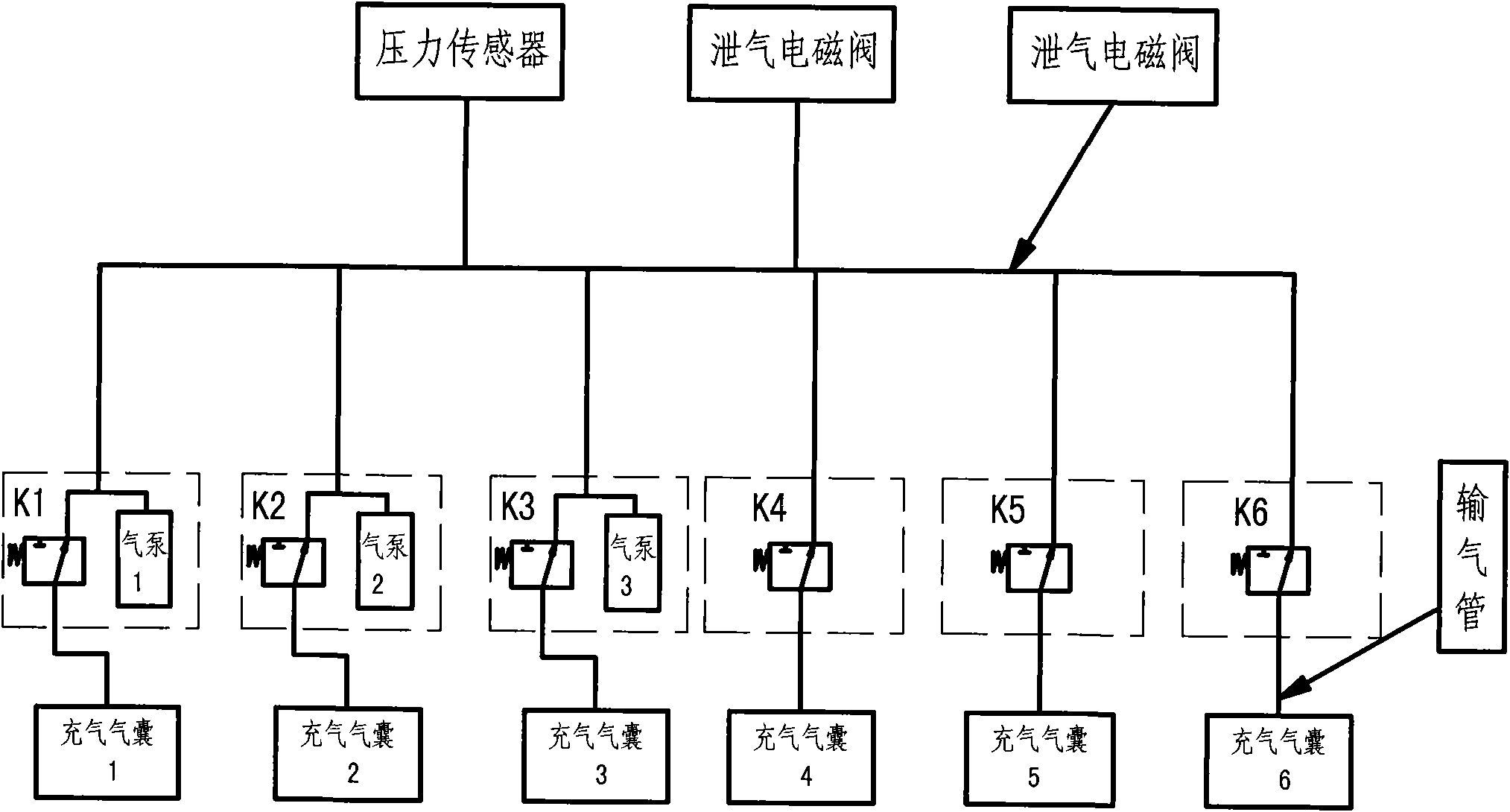
[0016] In the air pressure wave therapy instrument involved in the present invention, the inflatable airbag group is composed of 1 to 10 inflatable airbags, and the number of air pumps installed on the inflatable airbag group is 1 to 3. This embodiment is an inflatable airbag composed of five inflatable airbags. The airbag group and three air pumps are described as examples, see figure 1 . Each inflatable airbag of the inflatable airbag group is connected with an air main pipe through an air delivery pipe, and a deflation solenoid valve and a pressure sensor are installed on the air main pipe, and an electromagnetic valve (K1 ~K6). The air pump 1, the air pump 2, and the air pump 3 are respectively directly installed on the inflatable air ...


PUM


Abstract

The invention relates to an air pressure wave therapeutic instrument, which comprises a control box, an air pump and an inflatable air bag group, wherein the air pump controls the inflatable air bag group; the control box controls the start and the stop of the air pump; each inflatable air bag in the inflatable air bag group is communicated with an air path main pipe by adopting an air pipe; a deflated solenoid valve and a pressure sensor are arranged on the air path main pipe; a solenoid valve is arranged on the pipeline of each air pipe; the inflatable air bag group is at least provided withone air pump; and the air pump is directly arranged on the inflatable air bags to form a whole with the air bags. The air pressure wave therapeutic instrument has simple structure and scientific andreasonable design; the adoption of arranging the air pump and the inflatable air bags into a whole saves overlong plastic air pipes, saves materials, improves the safety performance of products, solves the problem of restriction to the using environmental conditions of equipment, shortens the time of inflating the inflatable air bags, and realizes pulse massage with higher frequency and better therapeutic effect.

Description

technical field [0001] The invention belongs to the field of medical equipment, in particular to a mechatronic air pressure wave therapy instrument. Background technique [0002] The air wave pressure therapy instrument widely used at present is composed of two parts: the main machine installed with the air pump and the inflatable air bag. One air pump supplies air to all the inflatable air bags. The form has the following disadvantages: 1. The air pump and the inflatable air bag are connected by a long plastic air tube. For an air wave pressure therapy instrument with multiple inflatable air bags, there are many plastic air tubes, which are cumbersome and messy, and the tow is heavy; especially in the In some places where the space is small, its installation and use will become extremely inconvenient. 2. During the inflation process of the inflatable airbag, the compressed air needs to pass through the trachea before reaching the inflatable airbag. A longer inflation pipel...

Claims


Application Information

Patent Timeline
Patent Type & Authority Applications(China)
IPC IPC(8): A61H9/00A61H1/00A61H7/00
Inventor 徐继铭王洪亮
Owner 天津市联大医用设备有限公司
Why Eureka
Try Eureka