
Fully automatic bucket-cleaning plant

A barrel washing device, a fully automatic technology, applied in the directions of cleaning hollow objects, cleaning methods and utensils, chemical instruments and methods, etc., can solve the problems of unsanitary, high production cost, and inability to remove dirt and scale.

Inactive Publication Date: 2010-03-03
宋树建
View PDF6 Cites 11 Cited by
  • Summary
  • Abstract
  • Description
  • Claims
  • Application Information

AI Technical Summary

Problems solved by technology

[0003] At present, various types of pure water barrels, oil barrels, chemical material barrels, etc., will produce a lot of dirt and scale in the barrels that cannot be removed after a long time of use.
There is no ideal cleaning equipment in the current domestic market, and some can only clean a small part of the dirt in the bucket, especially pure water buckets. The small mouth of the bucket cannot be cleaned with a larger brushing tool into the bucket, so sometimes manual cleaning is required. Put the buckets into the river sand and cleaning agent and shake them. One person can only clean a few buckets a day. This method of work is slow, employs a large number of people, is unhygienic, and unsafe; the production cost is high. It is difficult for various pure water plants a problem solved

Method used


Image

  • Fully automatic bucket-cleaning plant
  • Fully automatic bucket-cleaning plant
  • Fully automatic bucket-cleaning plant

Examples


Embodiment Construction

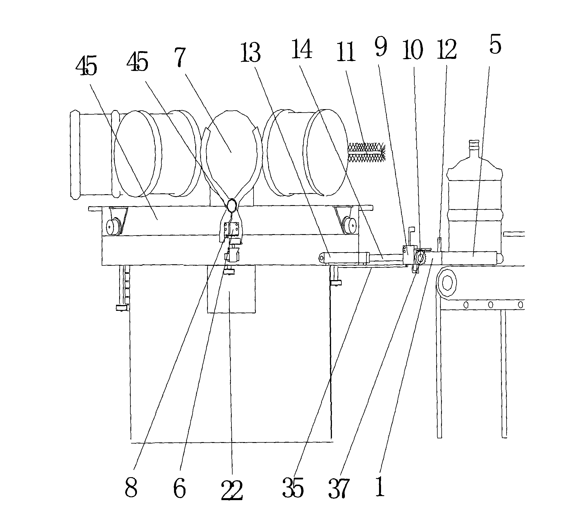
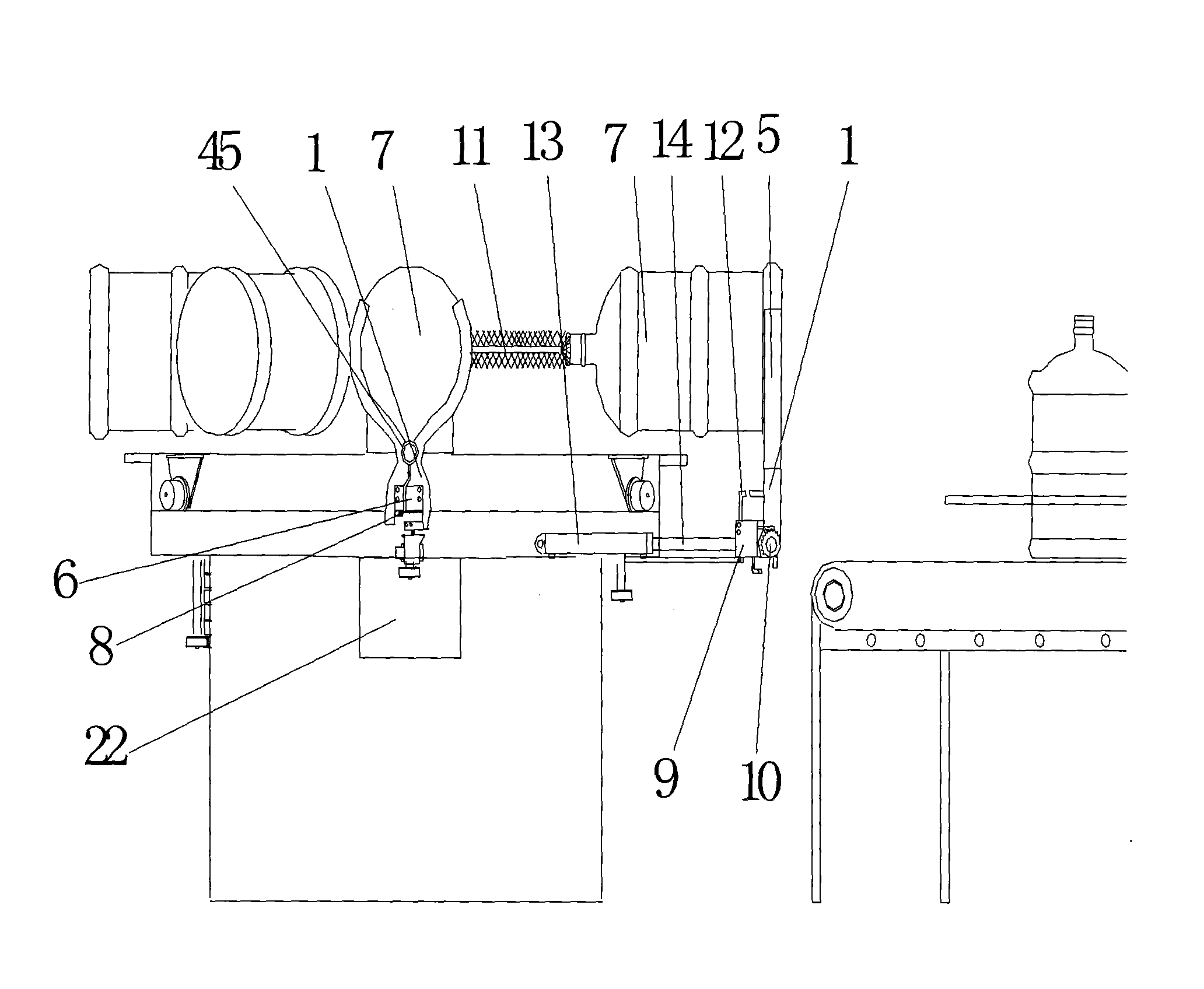
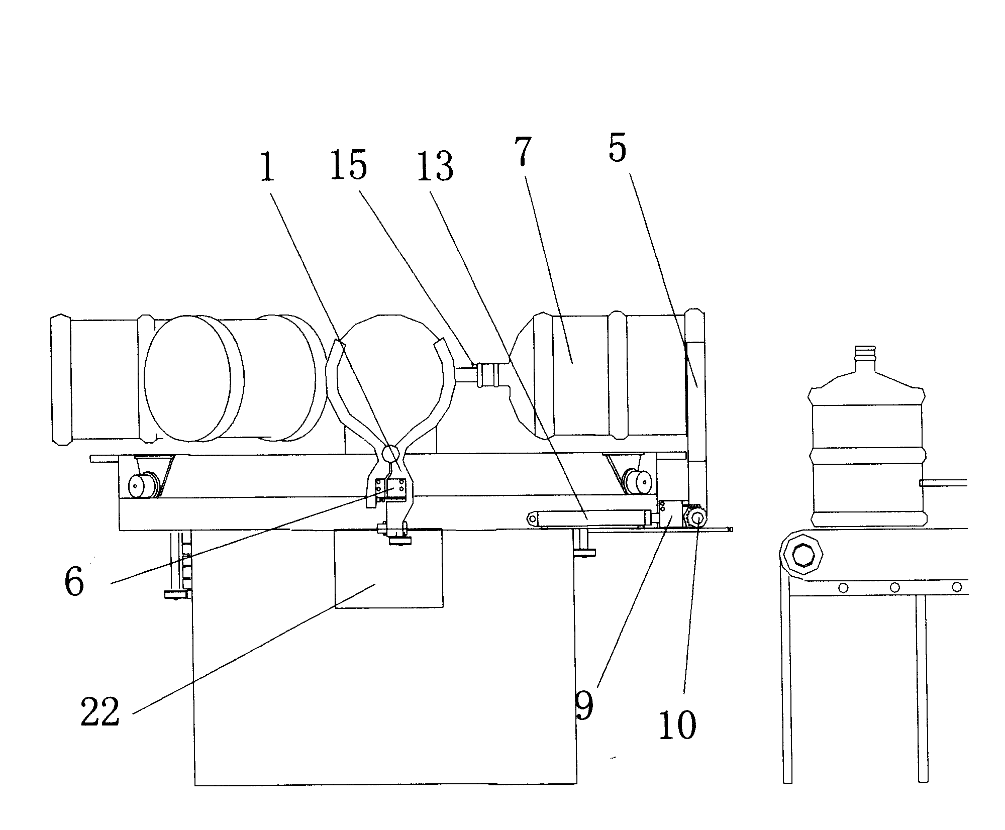
[0014] This cleaning device is mainly composed of a barrel clamping device (1), a cleaning device (2), a power rotating part (3) and a conveying part (4). Wherein the bucket clamping device (1) is provided with clamping bucket pliers (5), when the solenoid valve (6) is powered on, the bucket clamping pliers (5) will put the bucket (7) under the suction force of the solenoid valve (6) The bottom is clamped firmly. At this moment, the button (8) connects the power supply of the electromagnetic valve (9), and the gear (10) is dragged by the rack in the electromagnetic valve (9) to make the barrel clamp rise and reach an angle of 90 degrees with the electromagnetic valve (9). Align the mouth of the water bucket (7) with the washer (11), and press the button switch (12) at the same time to cut off the power to the cylinder (13). In (7), when the switch (15) of the washer (11) is pressed down by the mouth of the bucket (7), the washer (11) is automatically opened in the bucket (7),...


PUM


Abstract

The invention relates to a fully automatic bucket-cleaning plant mainly comprising a bucket-clamping device, a cleaning device, a power rotation part, a conveying part and the like, wherein the bucket-clamping device is provided with a pair of bucket-clamping pincers, and the bucket-clamping pincers firmly clamp a bucket under the suction of an electromagnetic valve. A rack in the electromagneticvalve drags a gear to enable the bucket-clamping pincers to rise to form an angle of 90 degrees with the electromagnetic valve. The mouth of the bucket is aligned to a cleaner, and a cylinder intake lever enables the cleaner to enter the bucket and to be opened in the bucket to carry out cleaning operation. The lever is wrenched to grip a gear ring and moves forward; a rotary table rotates once every 3 seconds, and the rotary table can rotate by 1 / 6 of the gear ring each time. Under the action of two worm wheels, the rotating speed per minute of the rotary table and the gear ring is reduced to200 rounds; when the rotary table rotates once, the bucket is rotated to the position of a conveyor, the lever rolls off the cylinder after the cleaning is completed to convey the bucket above a conveyer belt; the gear rotates outwards to put down the bucket-clamping pincers, a spring pushes a screw out to enable the screw to rotate 180 degrees, and the mouth of the bucket is downwards aligned tothe bucket pit of the conveyer belt, under the action of the spring, the bucket-clamping device puts down the bucket, and at the time, a switch bounces, enabling the electromagnetic valve to be powered on, and then the screw rotates 180 degrees so as to enable the bucket-clamping device to be restored to the original working state.

Description

[0001] The technical field [0002] The invention relates to a cleaning device, more specifically to a water bucket, a chemical bucket, and especially cleaning equipment for small-diameter containers. Background technique [0003] At present, various types of pure water barrels, oil barrels, chemical material barrels, etc. will produce a lot of dirt and scale in the barrels that cannot be removed after a long time of use. There is no ideal cleaning equipment in the current domestic market, and some can only clean a small part of the dirt in the bucket, especially pure water buckets. The small mouth of the bucket cannot be cleaned with a larger brushing tool into the bucket, so sometimes manual cleaning is required. Put the buckets into the river sand and cleaning agent and shake them. One person can only clean a few buckets a day. This method of work is slow, employs a large number of people, is unhygienic, and unsafe; the production cost is high. It is difficult for various p...

Claims


Application Information

Patent Timeline
IPC IPC(8): B08B9/20B08B9/42B08B9/44
Inventor 宋树建宋春辑
Owner 宋树建
Learn More