

Lunar exploration mechanical arm modular joint with torque retention feature
A technology of modular joints and robotic arms, applied in manipulators, manufacturing tools, joints, etc., can solve the problems of short service life of robotic arms and high launch cost of lunar rover, and achieve high overall bending rigidity, compact structure, location High-precision output
- Summary
- Abstract
- Description
- Claims
- Application Information
AI Technical Summary
Problems solved by technology
Method used
Image

Examples
specific Embodiment approach 1
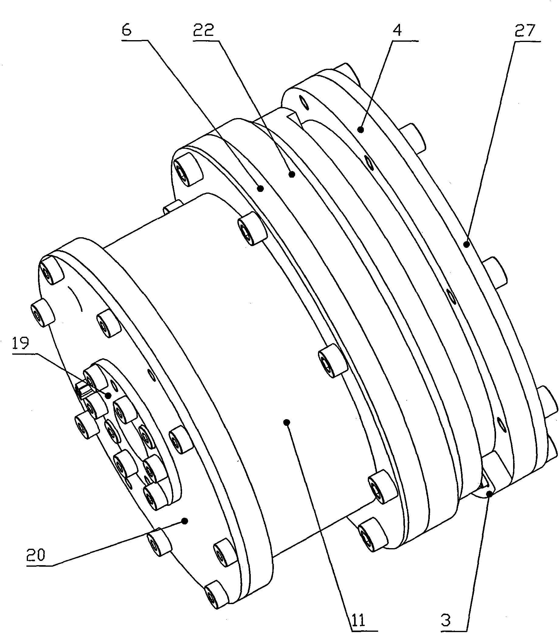
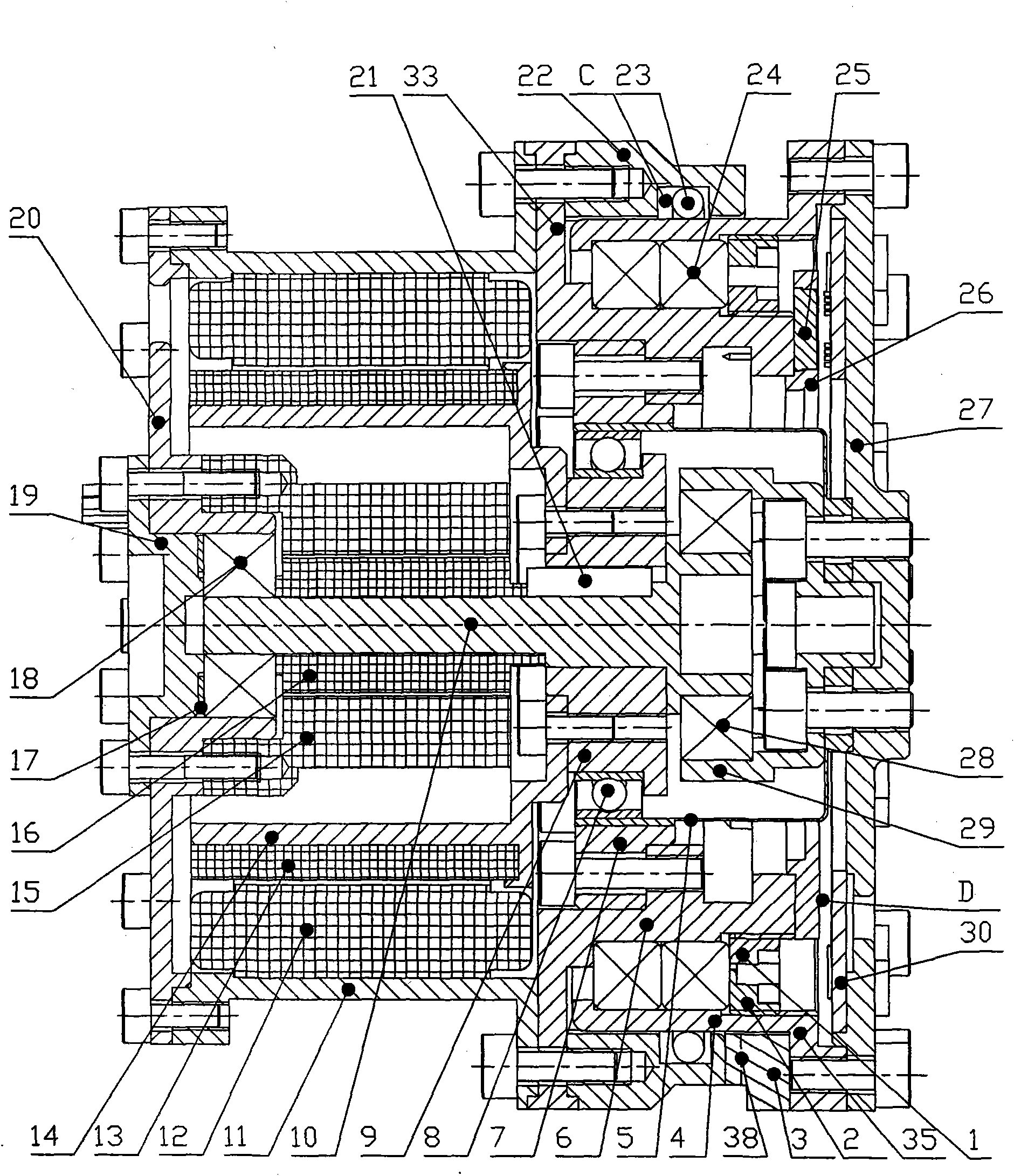
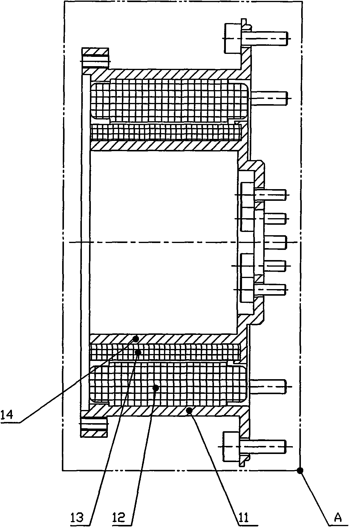
[0007] Specific implementation mode one: combine Figure 1-14 and Figure 20 as well as Figure 21 To illustrate this embodiment, the modular joint of the lunar exploration manipulator with torque retention characteristics in this embodiment is composed of an input device A, an output device B, a sealing device C and an electrical device D; the input device A is composed of a drive device and an input device The casing 11 is composed of; the driving device is installed in the input device casing 11, and the driving device is composed of a DC brushless motor stator 12, a DC brushless motor rotor 13 and a motor rotor shaft 14, and the DC brushless motor stator 12 is installed in the input device. On the inner wall of the device housing 11, the motor rotor shaft 14 is set in the input device housing 11, and the DC brushless motor rotor 13 is set on the motor rotor shaft 14; the sealing device C is composed of a sealing device flange 22 and an O-ring 23 The output device B consi...
specific Embodiment approach 2
[0008] Specific implementation mode two: combination figure 2 , Figure 4 and Figure 5 Describe this embodiment, the resolver transmission device of this embodiment is comprised of first radial bearing 28, resolver input shaft 10, key 21, resolver stator 15, resolver rotor 16, second radial bearing 18, second diameter It consists of a bearing support seat 20, an adjusting gasket 17 and a second radial bearing cover 19; the inner ring of the first radial bearing 28 is supported on the right end of the resolver input shaft 10, and the outer ring of the first radial bearing 28 is sleeved on In the bearing seat of the flange plate 29 at the output end of the harmonic reducer; the left end of the resolver input shaft 10 is sleeved in the inner ring of the second radial bearing 18, and the second radial bearing 18 is sleeved in the second radial bearing support seat 20 In the bearing seat, the second radial bearing gland 19 is pressed into the support seat 20 from the left side ...
specific Embodiment approach 3
[0009] Specific implementation mode three: combination figure 2 , Figure 15 ~ Figure 19 Describe this embodiment, the electric device D of this embodiment is potentiometer; Said potentiometer is made up of brush 42, brush holder 25, brush holder base flange 26, conductive ring 41 and potentiometer plate 30, The brush 42 is fixed on the brush holder 25, and the brush holder 25 is installed in the mounting hole 46 of the flange 26 of the brush holder base, and the flange 26 of the brush holder base is fixedly connected with the inner seat 6 of the angular contact bearing , the brush holder 25 and the flange 26 abut against the bearing inner seat 6 to realize the fixation of the brush holder assembly, the conductive ring 41 is pasted on the potentiometer plate 30, and the potentiometer plate 30 is fixedly connected to the output flange 27 . The rotation angle of the joint is measured by sliding the brush 42 on the conductive ring 41; the absolute position of the joint is meas...
PUM
 Abstract
Description
Claims
Application Information