
Automobile brake friction plate alarm method and device thereof

A friction plate and brake technology, which is applied in the field of automotive brake friction plate alarms, can solve problems such as weakened performance, failure to warn drivers and passengers, and influence on driving safety, and achieve simple structure, easy assembly and transportation, and improved safety performance. Effect

Active Publication Date: 2010-03-03
CHERY AUTOMOBILE CO LTD
View PDF0 Cites 6 Cited by
  • Summary
  • Abstract
  • Description
  • Claims
  • Application Information

AI Technical Summary

Problems solved by technology

Although the aforementioned two alarms for the wear limit can give an alarm when the life of the friction plate is at the limit, they cannot warn the driver and occupants of the fault or failure during the use of the friction plate, and when the friction plate does not reach the wear limit During the normal use before, due to a failure of some (some) parts in the brake system, such as wheel cylinder stuck, residual pressure in the pipeline, rusted or deformed guide rod, etc., the friction plate and the brake system The dragging of the moving disc often occurs
[0003] Friction plate dragging will lead to a sharp increase in fuel consumption of the vehicle, resulting in overheating of the friction plate body, weakened performance, and reduced braking performance, which will affect driving safety. Vicious circle, resulting in brake failure
Moreover, dragging also has a direct impact on the life of the friction plate
If the brake on one side wears out, it will cause driving deviation and braking deviation, which will seriously affect driving safety

Method used


Image

  • Automobile brake friction plate alarm method and device thereof
  • Automobile brake friction plate alarm method and device thereof
  • Automobile brake friction plate alarm method and device thereof

Examples


Embodiment Construction

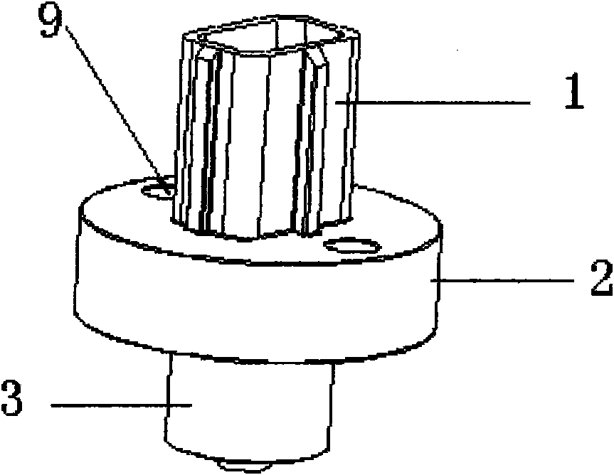
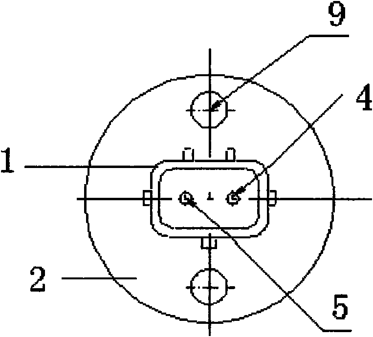
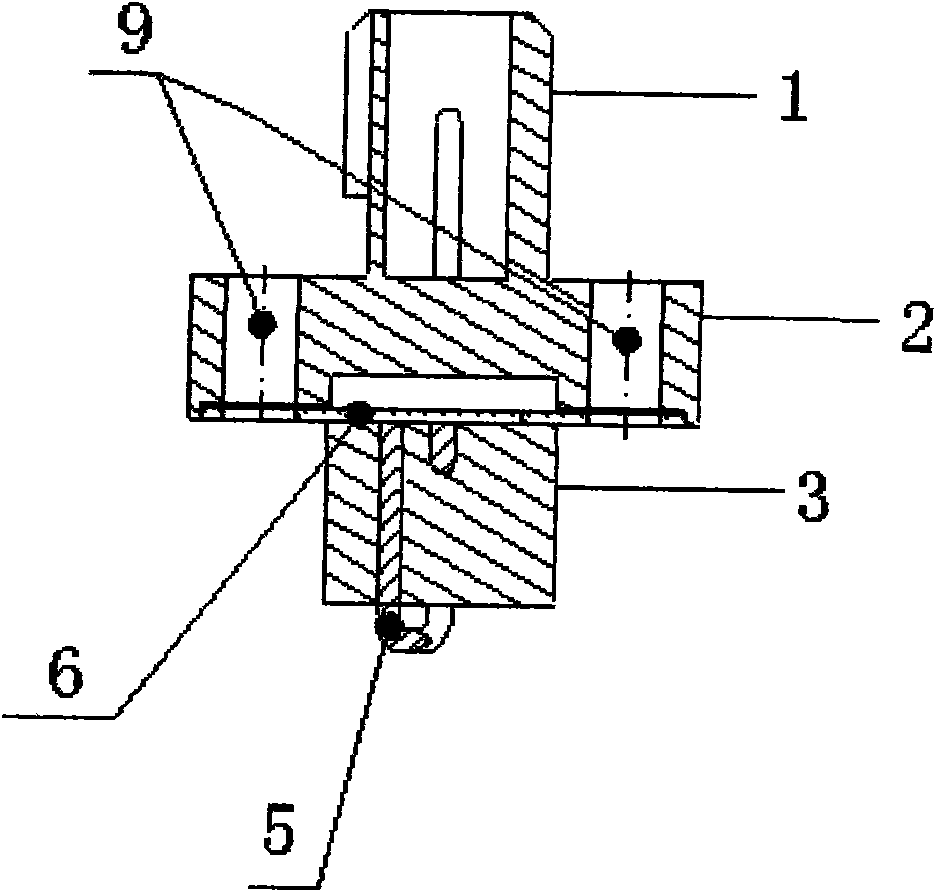
[0024] Such as Figures 1 to 4 As shown, the sensor housing is divided into the connector part 1, the friction plate back plate fixing part 2, and the pin fixing part 3 from top to bottom. There are pin 4, pin 5 and copper piece 6 inside the sensor housing. The upper contact of the two pins is located in the connector part 1 of the housing, and the upper contact of the two pins is connected to the vehicle control circuit. The lower contacts of the two pins are located in the pin fixing part 3 of the housing, and the lower contacts of the two pins are connected to the copper sheet 6. There is a space for the copper sheet to bulge upward when heated, and the two ends of the copper sheet are fixed. hole. The lower part of the pin 5 is U-shaped, and the bottom of the pin passes through the sensor housing.

[0025] Such as Figure 5 , Image 6 As shown, the sensor is fixed to the back plate 8 of the friction plate through the fixing hole 9 on the shell, the pin fixing part 3 o...


PUM


Abstract

The invention relates to an automobile brake friction plate alarm method and a device thereof, which can effectively monitoring the working state of a friction plate and alarm in time. The invention has the technical scheme that the friction plate is provided with a sensor; when the thickness of the friction plate reaches wear limit or the friction plate has overhigh temperature after being drag ground for a long time, the sensor provides a signal for a finished vehicle control circuit which leads an alarm lamp on an instrument panel to be lightened.

Description

technical field [0001] The invention relates to an alarm method and device for an automobile brake friction plate. Background technique [0002] Existing automobile brake friction disc alarm forms or report to the police in the form of breaking the electronic circuit, or send harsh screams to remind drivers and passengers that the friction disc wear has reached the limit with the friction mechanical alarm spring. Although the aforementioned two alarms for the wear limit can give an alarm when the life of the friction plate is at the limit, they cannot warn the driver and occupants of the fault or failure during the use of the friction plate, and when the friction plate does not reach the wear limit During the normal use before, due to a failure of some (some) parts in the brake system, such as wheel cylinder stuck, residual pressure in the pipeline, rusted or deformed guide rod, etc., the friction plate and the brake system The dragging of the moving disc often occurs. [...

Claims


Application Information

Patent Timeline
Patent Type & Authority Applications(China)
IPC IPC(8): B60T17/22G01B5/06G01K5/52
Inventor 贾占辉
Owner CHERY AUTOMOBILE CO LTD
Learn More