Support frame of adjustable suspension scaffold
A cantilevered scaffolding and adjustable technology, which is applied to the accessories of scaffolding, house structure support, house structure support and other directions, can solve the problems of poor positioning accuracy of vertical poles, increase the cost of use, and cannot be folded, and achieves improved positioning accuracy, The effect of saving the cost of use and reducing the space occupied
Inactive Publication Date: 2010-03-03
江苏金土木建设集团华顺工程有限公司
View PDF0 Cites 21 Cited by
- Summary
- Abstract
- Description
- Claims
- Application Information
AI Technical Summary
Problems solved by technology
The problems of the above-mentioned structure are: First, the versatility is relatively poor. Since the horizontal beam and the diagonal brace are fixedly connected by welding, when the frame is completed, the included angle is constant, and the relevant geometric dimensions cannot be changed. However, in different projects The height of the mid-floor and the horizontal distances of the outer axes of the upper and lower floors cannot be exactly the same, resulting in a finished frame that can only be reused in construction projects with similar geometric dimensions; secondly, the loss of materials is large, d
Method used
View moreImage
Smart ImageViewing Examples

Examples
 PUM
 Abstract
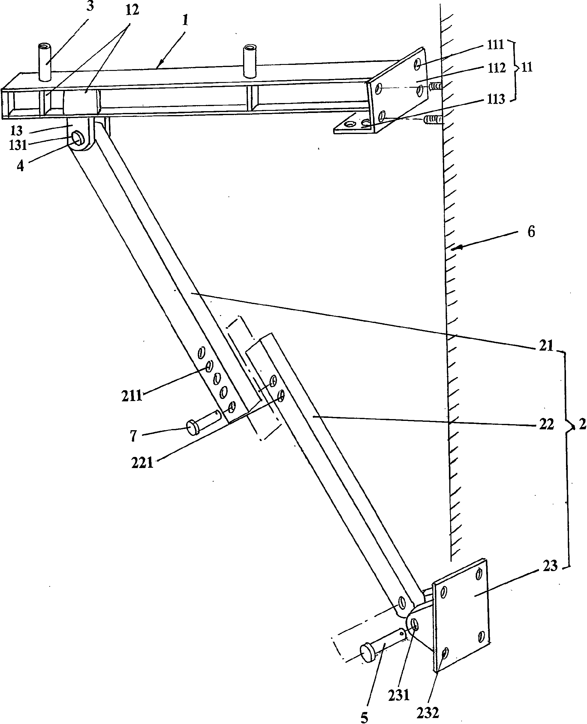
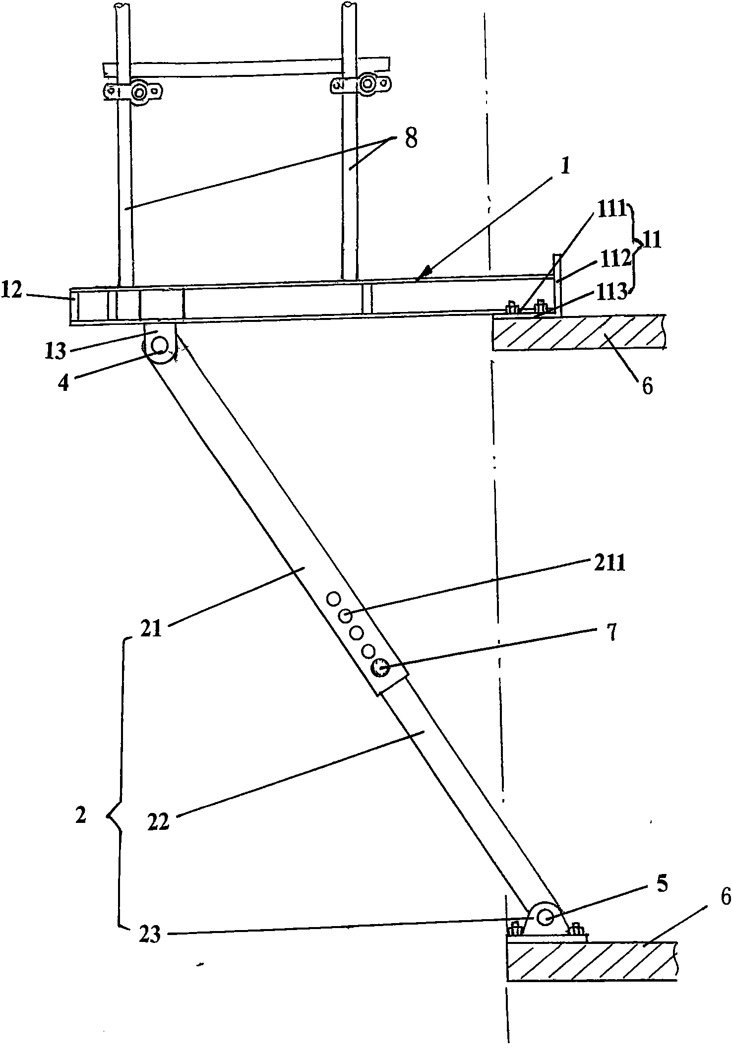
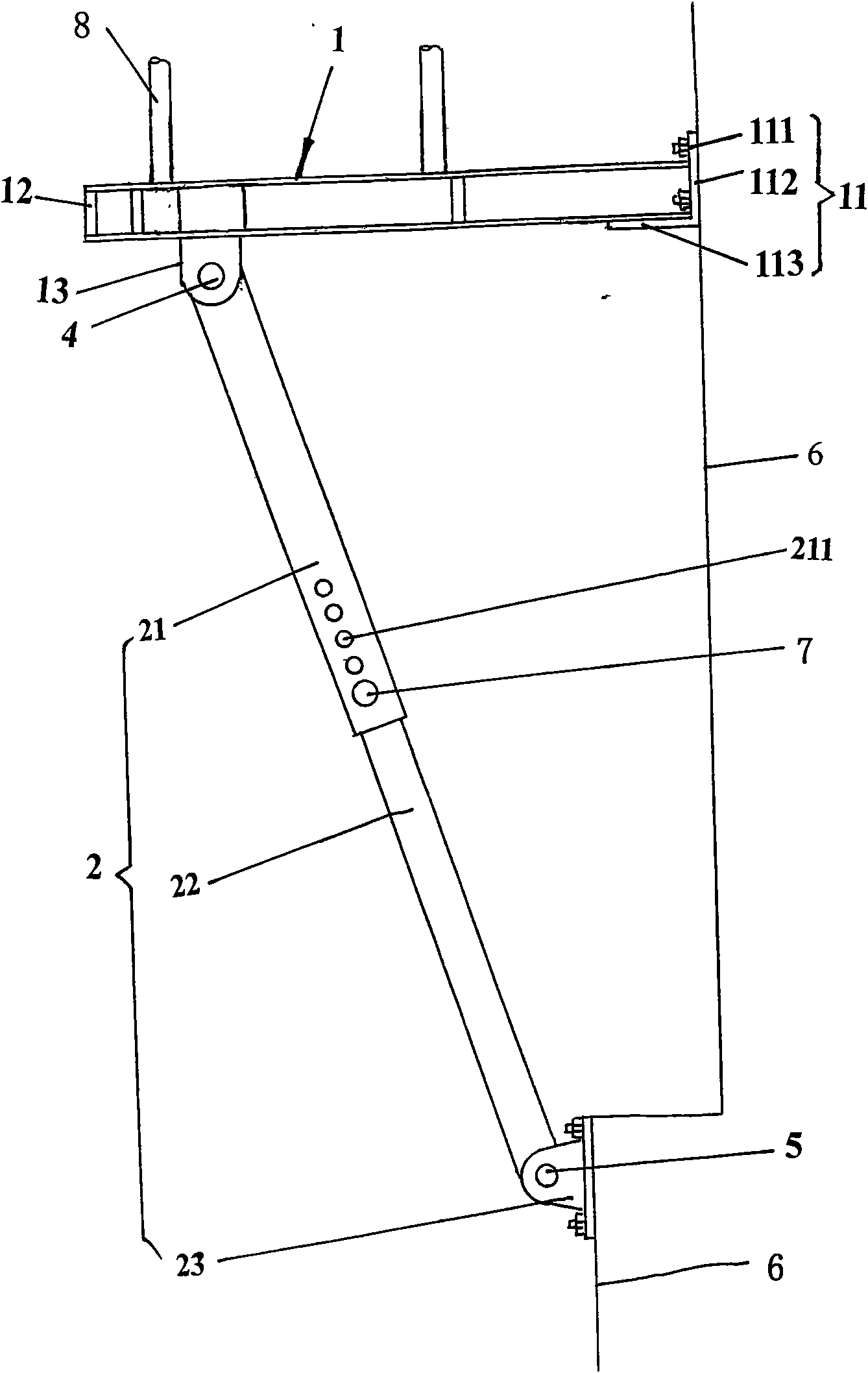
The invention relates to a support frame of an adjustable suspension scaffold, belonging to technical field of building construction. The support frame of the adjustable suspension scaffold comprisesa horizontal beam, a bracing and locating elements arranged on the horizontal beam at intervals. The support frame of the adjustable suspension scaffold is characterized in that one end of the horizontal beam is provided with a connecting lug; the other end of the horizontal beam is provided with a fixed plate of the horizontal beam; a first bolt hole for connecting a main body of a building is arranged on the fixed plate of the horizontal beam; the bracing consists of a first sleeve and a second sleeve; one end of the first sleeve is articulated with the connecting lug on the horizontal beamvia a first pin shaft; the other end of the first sleeve is inserted in one end of the second sleeve and fixed by an adjusting pin shaft; the other end of the second sleeve is articulated with a bracing fixed seat via the second pin shaft; and a second bolt hole for connecting the main body of the building is arranged on the bracing fixed seat. The invention has the advantages of reducing the occupied space, facilitating the transportation, storage and installation, having strong universality, saving material and improving the positioning precision of a scaffold upright.
Description
technical field [0001] The invention relates to an adjustable cantilevered scaffold support frame, which belongs to the technical field of building construction. Background technique [0002] Generally, scaffolding is required for the construction of the main body of high-rise buildings. There are two main types of scaffolding currently used. One is floor-standing scaffolding, which is erected from the ground until the building is capped. After the building is completed, it will be dismantled. This kind of scaffolding requires a lot of one-time investment, long turnover period, low efficiency, long construction period, and high project cost. At the same time, there are potential safety hazards due to the large amount of high-altitude operations; the other is cantilevered scaffolding, which is composed of scaffolding and used to install Composed of cantilevered scaffolding support frames, this kind of scaffolding has the advantages of reusable scaffolding materials, short con...
Claims
Login to View More Application Information
Patent Timeline
 IPC IPC(8): E04G5/04
Inventor 张建忠周健王志刚刘生华徐义军
Owner 江苏金土木建设集团华顺工程有限公司