Backlight module

A backlight and light source technology, applied in the field of backlight modules, can solve the problems of large thickness of direct-lit backlight modules, inability to meet the needs and development trends of display thinning, and inability to apply thin LCDs, etc. The effect of high brightness requirements

Inactive Publication Date: 2010-03-03
BOE TECH GRP CO LTD
View PDF0 Cites 17 Cited by
  • Summary
  • Abstract
  • Description
  • Claims
  • Application Information

AI Technical Summary

Problems solved by technology

However, since the light source needs to occupy a certain space and requires a certain light mixing distance, the thickness of the direct-lit backlight module is relatively large. Even when the astigmatism lens or astigmatism mirror technology is used, the current minimum thickness reaches 30mm-40mm. It cannot be applied to thin LCDs, and cannot meet the needs and development trends of thin displays in the future

Method used


Image

  • Backlight module
  • Backlight module
  • Backlight module

Examples


Embodiment Construction

[0018] The technical solutions of the present invention will be described in further detail below with reference to the accompanying drawings and embodiments.

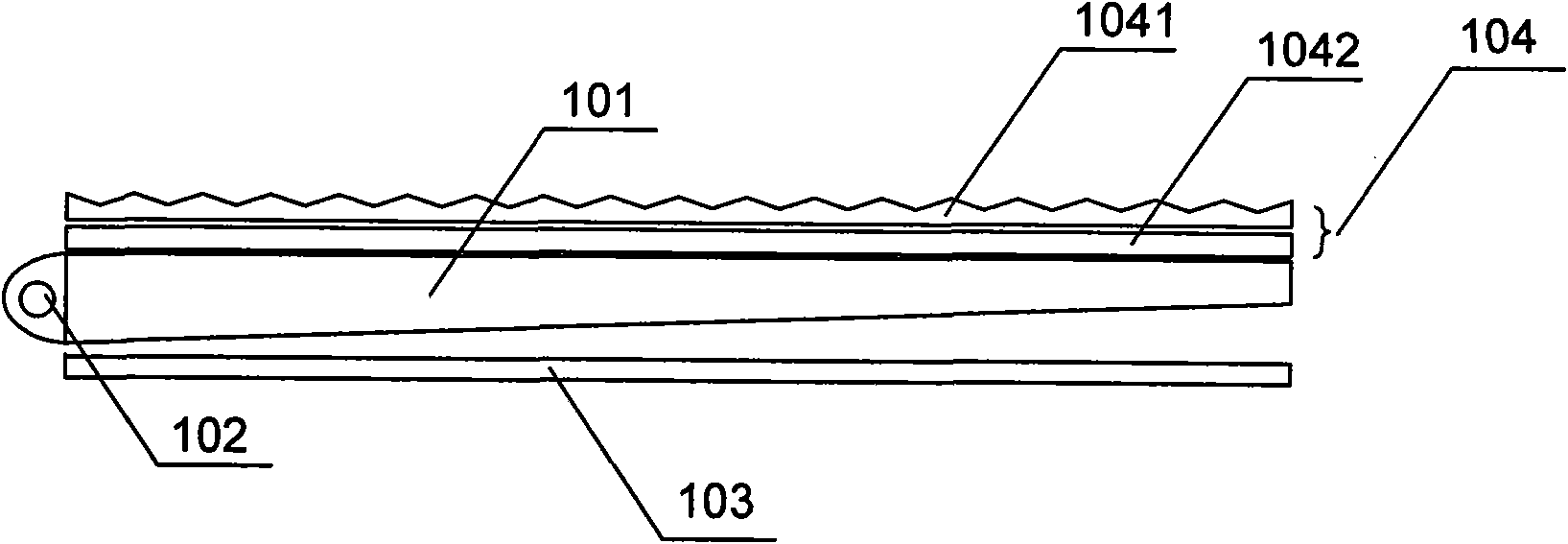
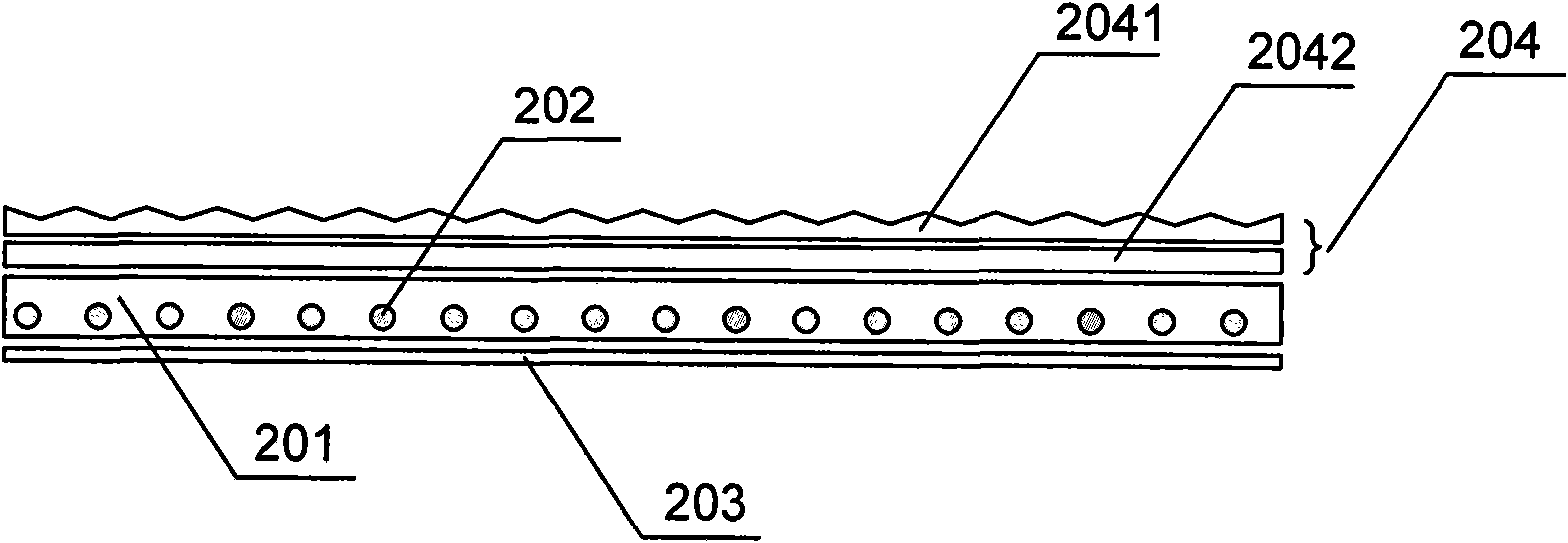
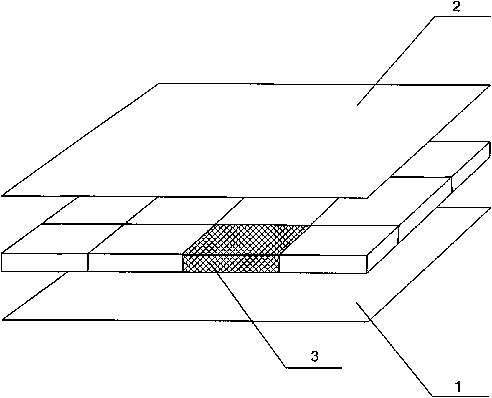
[0019] like image 3 As shown, it is a schematic structural diagram of an embodiment of the backlight module of the present invention, Figure 4 It is a cross-sectional view of an embodiment of the optical unit in the backlight module of the present invention. Please also see image 3 and Figure 4 , The backlight module provided by the embodiment of the present invention includes: a bottom reflection plate 1 and a light-emitting optical film group 2 , and one or more optical units 3 are arranged between the bottom reflection plate 1 and the light-emitting optical film group 2 . Each optical unit 3 includes a light guide plate 31 . The light guide plate 31 may be a polymethyl methacrylate (Polymethyl Methacrylate, hereinafter referred to as: PMMA) product or a polycarbonate (Polycarbonate, hereinafter referred to a...


PUM


Abstract

The invention relates to a backlight module, which comprises a bottom reflecting plate and a light exit membrane group, wherein one or more optical units are arranged between the bottom reflecting plate and the light exit membrane group; each optical unit comprises a light guide plate; the lower surface of each light guide plate is provided with one or more grooves; one or more light emitting units are arranged in each groove; and each light emitting unit comprises a circuit board and one or more light sources arranged on the circuit board. The backlight module is reduced in thickness and canmeet the requirements of large-sized LCDs and the demands for brightness.

Description

technical field [0001] The invention relates to the technical field of liquid crystal display, in particular to a backlight source module. Background technique [0002] Currently, among various flat panel displays, a liquid crystal display (Liquid Crystal Display, hereinafter referred to as LCD) has become a mainstream. Since the liquid crystal itself does not emit light, an external light source needs to be installed in the LCD, and the light emitted by the external light source is transmitted or reflected on the liquid crystal layer for image display. According to the way the LCD utilizes the light emitted by the backlight source, the LCD can be divided into a reflective LCD and a transmissive LCD. Most existing LCDs use the transmissive type. The backlight module is the main component of the LCD. Therefore, the thickness of the backlight module directly determines the thickness of the LCD. To realize an ultra-thin LCD, it is necessary to reduce the thickness of the backl...

Claims


Application Information

Patent Timeline
Patent Type & Authority Applications(China)
IPC IPC(8): F21V8/00F21V7/05F21V13/00G02F1/13357G02B6/00G02B1/04F21Y101/02
Inventor 万丽芳孙小斌张丽蕾赵星星邵喜斌王刚
Owner BOE TECH GRP CO LTD
Why Eureka
Try Eureka