
Mini laser scanning device and portable terminal thereof

A technology of laser scanning device and portable terminal, which is applied in the direction of electromagnetic radiation induction, TV, telephone structure, etc. It can solve the problems of large space, affecting laser scanning time, and low swing frequency, so as to improve detection efficiency, shorten scanning time, The effect of increasing the swing frequency

Inactive Publication Date: 2010-03-03
SHENZHEN MINDE ELECTRONICS TECH
View PDF0 Cites 11 Cited by
  • Summary
  • Abstract
  • Description
  • Claims
  • Application Information

AI Technical Summary

Problems solved by technology

When it is adapted to various modeling parts, it needs to occupy a large space, which greatly limits the scope of application and cannot be integrated into some small portable terminals
[0003] In addition, due to the large overall size, the swing frequency of the swing mirror of the current micro-laser scanning device is low, generally 20 Hz
However, its swing frequency directly affects the laser scanning time, which cannot improve the operation efficiency.

Method used


Image

  • Mini laser scanning device and portable terminal thereof
  • Mini laser scanning device and portable terminal thereof
  • Mini laser scanning device and portable terminal thereof

Examples


Embodiment Construction

[0026] The preferred embodiments of the present invention will be described in detail below with reference to the drawings.

[0027] The pattern mentioned in the patent document of the present invention refers to the barcode pattern composed of black bars and white spaces, or other patterns with different reflectivity to laser light due to different colors or different gray scales.

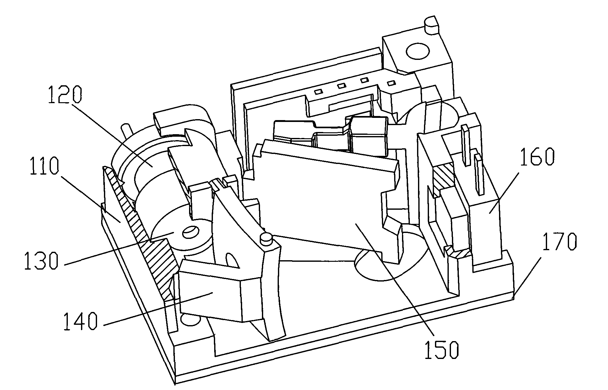
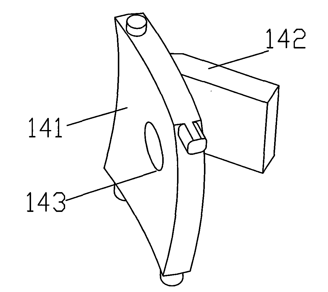
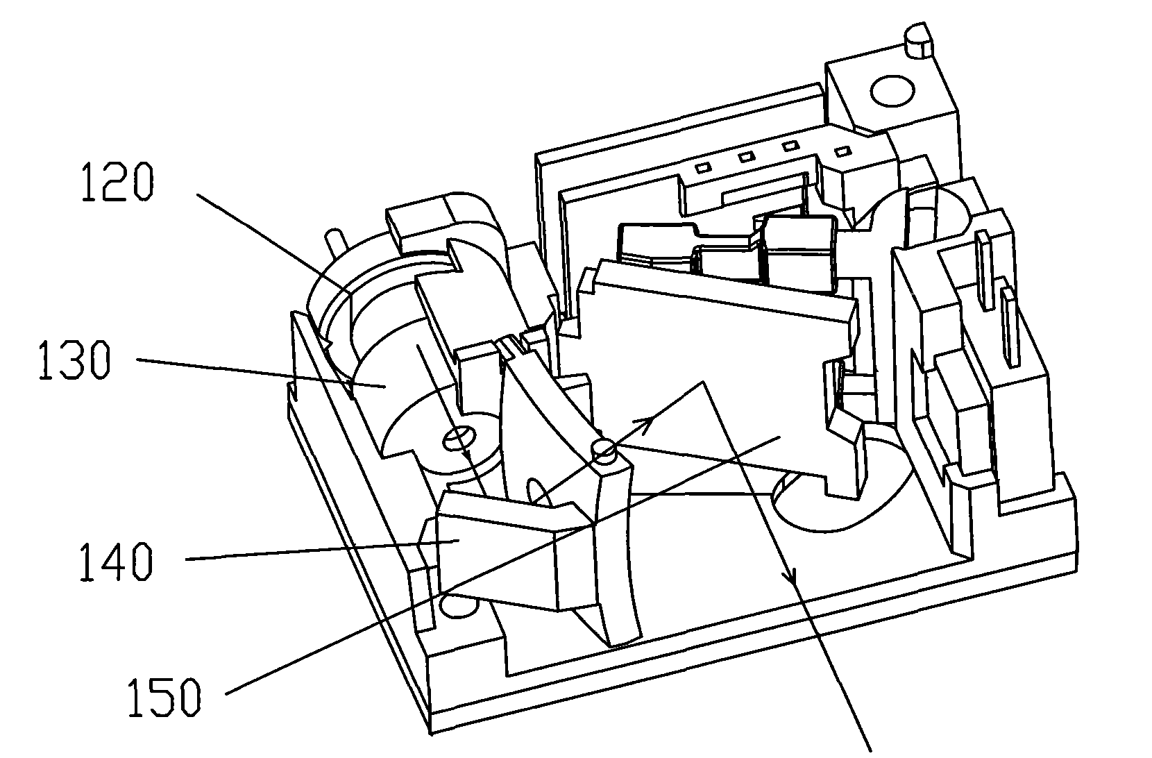
[0028] The micro laser scanning module structure of the embodiment of the present invention is as follows figure 1 As shown, it mainly includes a laser emitting module 120 fixed on a base 110, a line condenser 130, a swing mirror 142 that can swing back and forth at a predetermined frequency, a photoelectric conversion module 160, a turning mirror 142, a point condenser 141 and a data processing module 170. Wherein, the laser emitter 120 is fixed in a housing on the base 110 .

[0029] In this embodiment, the steering mirror 142 and the point condenser mirror 141 are connected in a V shape to fo...


PUM

PropertyMeasurementUnit
Angleaaaaaaaaaa

Abstract

The invention relates to a mini laser scanning device and a portable terminal thereof. The mini laser scanning device comprises a laser transmitter module, a line optical collector, a swaying mirror,a photoelectric conversion module, a steering mirror, a dot optical collector and a data processing module for acquiring pattern information by scanning with laser, wherein the steering mirror and thedot optical collector are in V-shaped connection, and the dot optical collector is provided with a hole for the laser which shoots at the swaying mirror after being steered via the steering mirror. By combining the steering mirror with the dot optical collector, the invention decreases the whole volume of the mini laser scanning device and realizes the laser scanning with tiny external dimensions. By promoting the swaying frequency of the swaying mirror, the scanning time is shortened and the detecting efficiency is promoted. Due to the tiny external dimensions, the invention can be widely applied to various devices, such as bar code data acquisition units, bar code scanners, portable digital terminals, etc.

Description

technical field [0001] The invention relates to a micro laser scanning device, in particular to the improvement of the light emission and light reflection structure of the micro laser scanning module. Background technique [0002] Due to the needs of the optical path of the current micro-laser scanning device, each component is generally arranged separately, so the overall size of the device is relatively large, and the typical size is: length 4.0 cm × width 2.8 cm × height 1.6 cm. When it is adapted to various molding parts, it needs to occupy a large space, so that the scope of application is greatly limited, and it cannot be integrated into some small portable terminals. [0003] In addition, due to the large overall size, the swing frequency of the swing mirror of the current micro laser scanning device is relatively low, generally 20 Hz. However, its swing frequency directly affects the laser scanning time, which cannot improve the operation efficiency. [0004] There...

Claims


Application Information

Patent Timeline
IPC IPC(8): G06K7/10H04N5/225H04M1/21
Inventor 许文焕易仰卿
Owner SHENZHEN MINDE ELECTRONICS TECH
Learn More