

Excimer lamp
An excimer lamp and discharge vessel technology, applied in the field of excimer lamps, can solve problems such as the destruction of the discharge vessel 61, and achieve the effects of preventing the destruction of the discharge vessel, preventing damage, and reducing ultraviolet strain
- Summary
- Abstract
- Description
- Claims
- Application Information
AI Technical Summary
Problems solved by technology
Method used
Image

Examples
Embodiment Construction
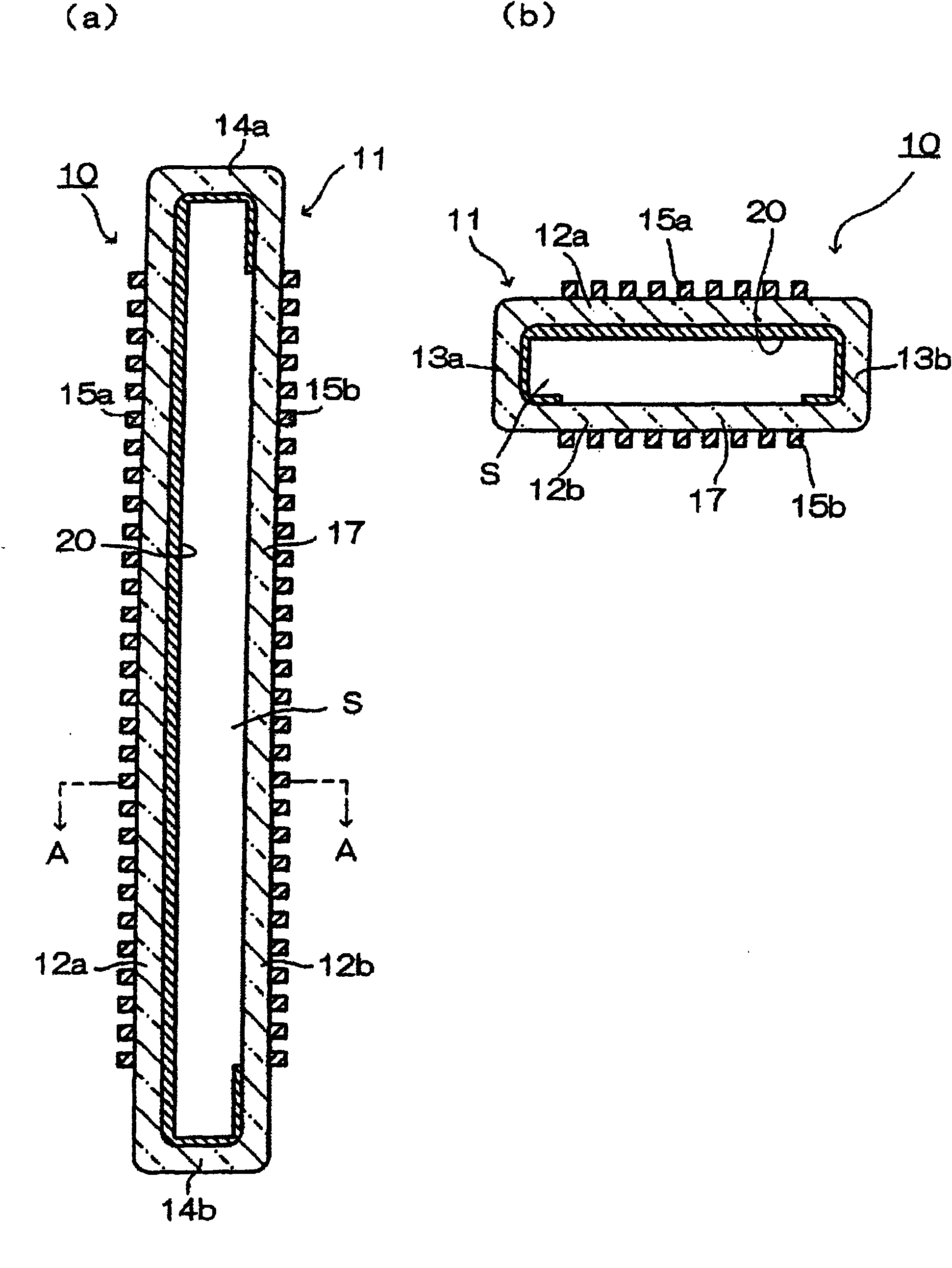
[0023] figure 1 It is an explanatory sectional view showing a schematic configuration of an example of the excimer lamp 10 of the present invention, figure 1 (a) is a cross-sectional view showing a section along the longitudinal direction of the discharge vessel 11, figure 1 (b) means figure 1 (a) A-A line sectional view.
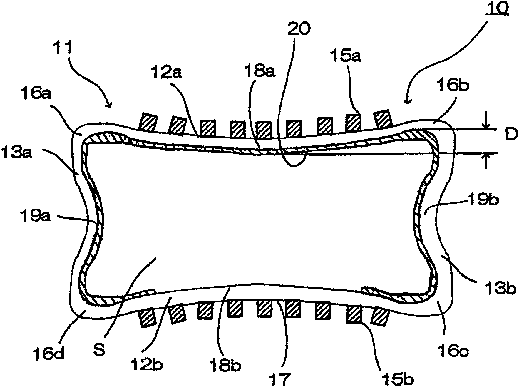
[0024] The excimer lamp 10 is equipped with a discharge vessel 11 having a rectangular cross-section and a hollow elongated discharge vessel 11 whose both ends are hermetically sealed and a discharge space S is formed inside. There is xenon. Here, the enclosing amount of xenon gas is such that the pressure is within a range of, for example, 10 to 60 kPa.
[0025] The discharge vessel 11 is made of silica glass such as synthetic quartz glass that transmits vacuum ultraviolet light well, and also functions as a dielectric.
[0026] In discharge vessel 11, long side surfaces 12a, 12b made of long plate glass are arranged to face each other, and short ...
PUM
 Abstract
Description
Claims
Application Information