
Chip package

A chip packaging and chip technology, which is applied in the direction of electrical components, electric solid devices, circuits, etc., can solve the problems of influence, tape is not suitable for mass production, and the reliability of chip packaging is difficult to control the thickness of liquid adhesive. Good for mass production

Inactive Publication Date: 2010-03-03
CHIPMOS TECH INC
View PDF0 Cites 0 Cited by
  • Summary
  • Abstract
  • Description
  • Claims
  • Application Information

AI Technical Summary

Problems solved by technology

The tape used here is not suitable for mass production because the tape must be cut to size before the die bonding process or die stacking process
In addition, the reliability of chip packaging can be affected by the difficulty in controlling the thickness of the liquid adhesive

Method used


Image

  • Chip package
  • Chip package
  • Chip package

Examples


Embodiment Construction

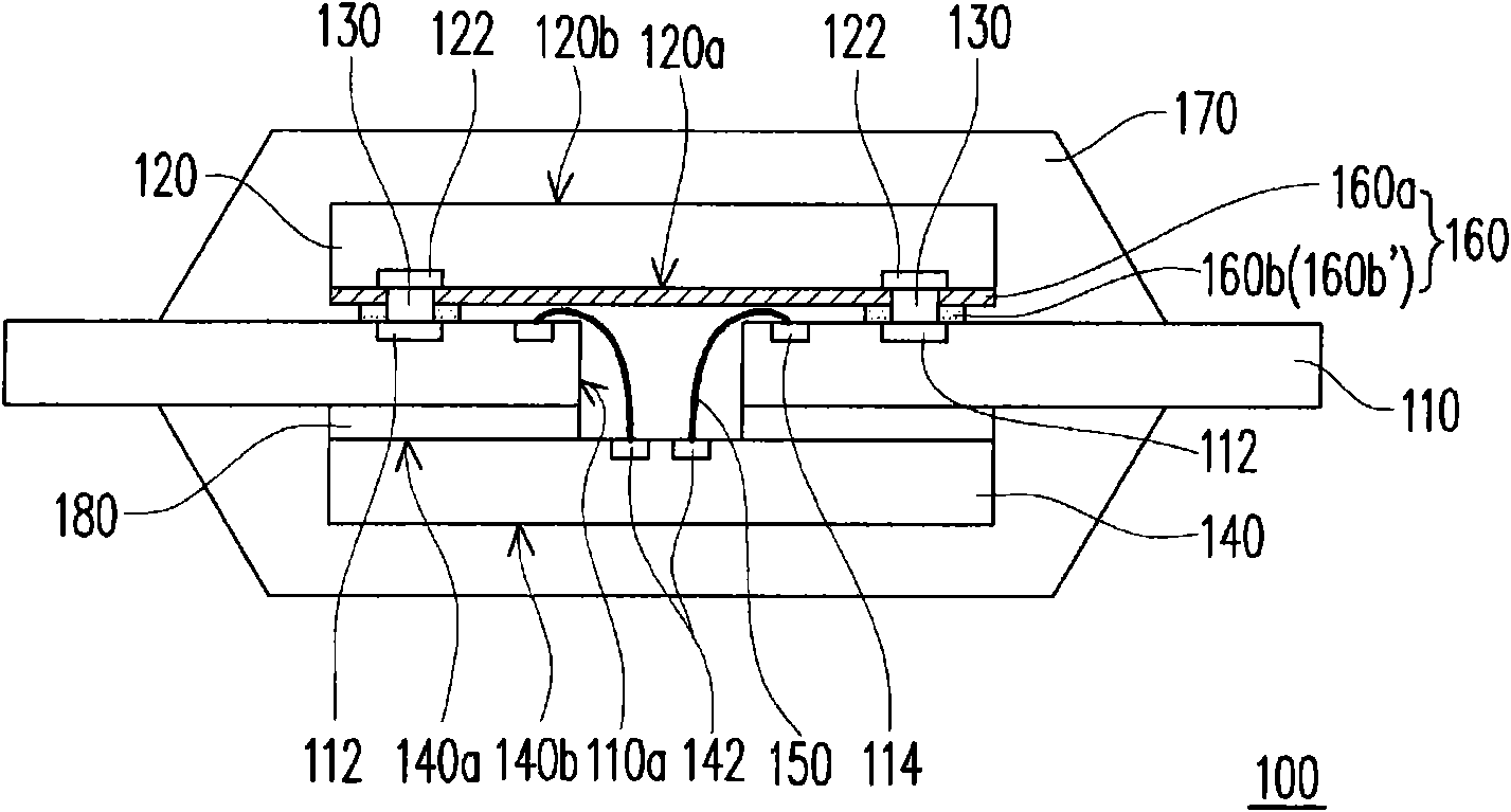
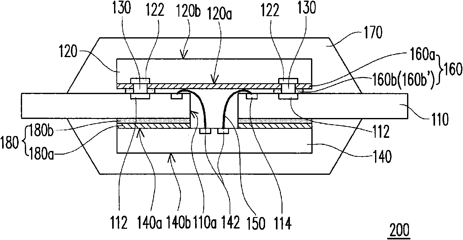
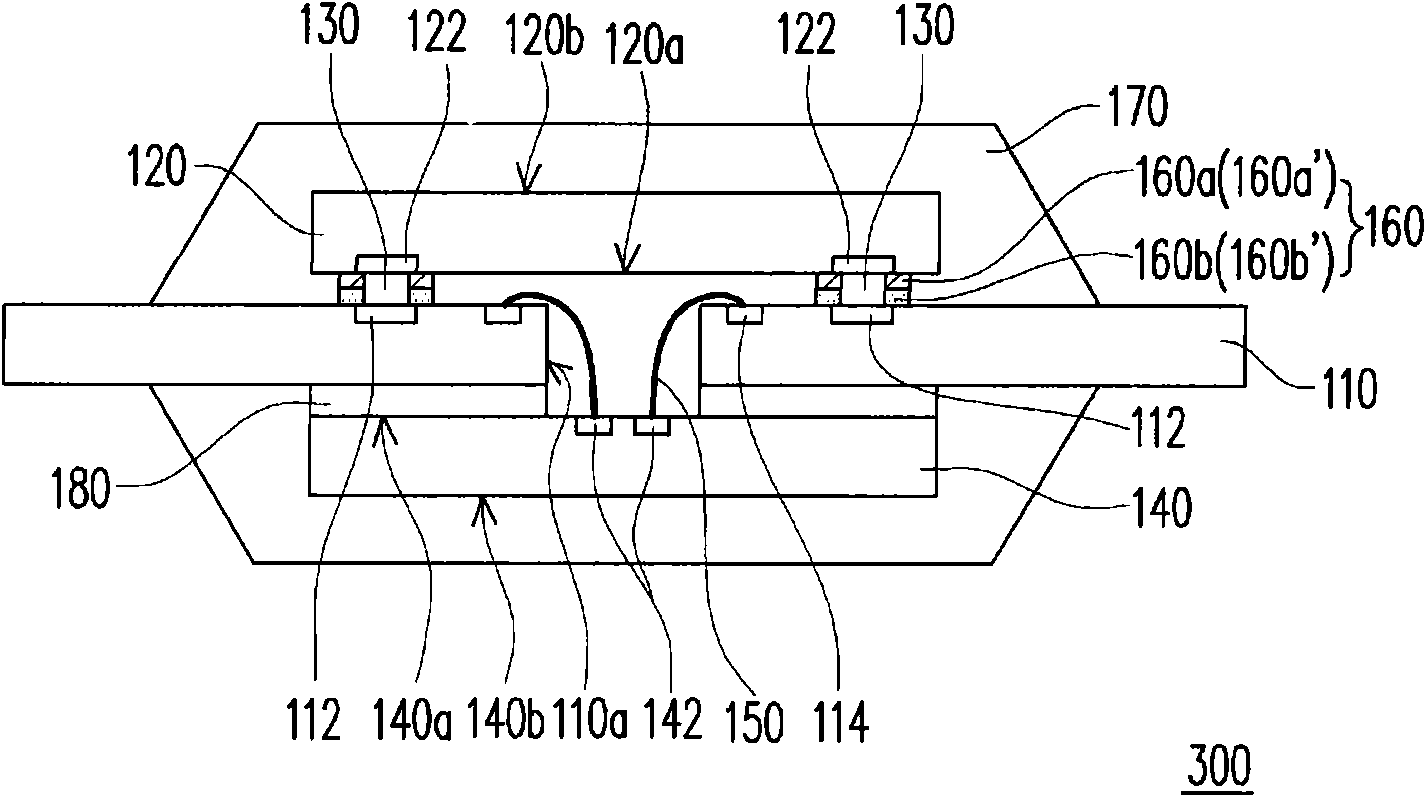
[0051] figure 1 It is a schematic cross-sectional view of a chip package according to the first embodiment of the present invention. Please refer to figure 1 , in this embodiment, the chip package 100 includes a carrier 110 having an opening 110a, a first chip 120, a plurality of bumps 130, a second chip 140, a plurality of bonding wires 150, a first adhesive layer 160 and an encapsulant 170 . The first chip 120 has a first active surface 120a and a first back surface 120b opposite to the first active surface 120a. The first chip 120 and the second chip 140 are disposed on the carrier 110 and located on two sides of the carrier 110 . The bumps 130 are disposed between the carrier 110 and the first active surface 120 a of the first chip 120 , and the first chip 120 is electrically connected to the carrier 110 through the bumps 130 . These bonding wires 150 are electrically connected to the carrier 110 and the second chip 140 , wherein each bonding wire 150 passes through th...


PUM


Abstract

A chip package including a bearing device with an opening, a first chip, a plurality of projecting blocks, a second chip, a plurality of bonding wires, a first adhesive layer and a package colloidal is provided. The first chip and the second chips are arranged at two sides of the bearing device. The projecting blocks arranged between the bearing deviceand a first active surface of the first chip and electrically connected to the first chip and the bearing device. The bonding wires pass through the opening of the bearing device and are electrically connected to the bearing device and the secondchip. The first adhesive layer adhered between the first active surface of the first chip and the bearing device. The first adhesive layer includes a first B-staged adhesive layer adhered on a firstactive surface of the first chip and a second B-staged adhesive layer adhered between the first B-staged adhesive layer and the bearing device.

Description

technical field [0001] The present invention relates to a chip package, and more particularly to a chip package capable of improving reliability and reducing production cost. Background technique [0002] In recent years, chip packages with multiple stacked chips have gradually been developed. Chip packaging is to stack multiple chips on top of a carrier and electrically connect to the carrier through bonding wires or bumps, where the bumps are gold bumps. bump), copper bump (copper bump), polymer bump (polymer bump) or solder bump (solder bump), and the carrier is, for example, a printed circuit board (print circuit board) or a lead-frame (lead-frame ). Generally, each chip stacked on a carrier can be adhered to other chips or carriers by glue such as tape or liquid adhesive. In particular, when using adhesive tape as an adhesive for a die-bonding process or a chip-stacking process, an adhesive tape of appropriate size and stickiness is attached to the die or carrier. W...

Claims


Application Information

Patent Timeline
IPC IPC(8): H01L25/00H01L23/10H01L23/31H01L23/488
CPCH01L2924/01005H01L2224/4824H01L2224/16225H01L2224/48091H01L2224/73215H01L2224/32225
Inventor 沈更新王伟
Owner CHIPMOS TECH INC
Learn More