
Manufacturing method of light guide unit and light guide unit

A technology of a light guide unit and a manufacturing method, which is applied to optical elements, light guides, optics, etc., can solve the problems of easy deformation of the surface of the reflective sheet, easy to see wavy stripes, etc., achieve thickness control, improve the phenomenon of wavy stripes, and reduce difficulty Effect

Inactive Publication Date: 2013-01-09
TOP VICTORY INVESTMENTS
View PDF5 Cites 3 Cited by
  • Summary
  • Abstract
  • Description
  • Claims
  • Application Information

AI Technical Summary

Problems solved by technology

However, in the process of laminating the light guide plate and the reflector, the surface of the reflector may be easily deformed and undulated due to pressing, so it is easy to see wavy stripes on the LCD panel, causing another problem

Method used


Image

  • Manufacturing method of light guide unit and light guide unit
  • Manufacturing method of light guide unit and light guide unit
  • Manufacturing method of light guide unit and light guide unit

Examples


Embodiment Construction

[0024] The present invention will be described in detail below in conjunction with the accompanying drawings and embodiments.

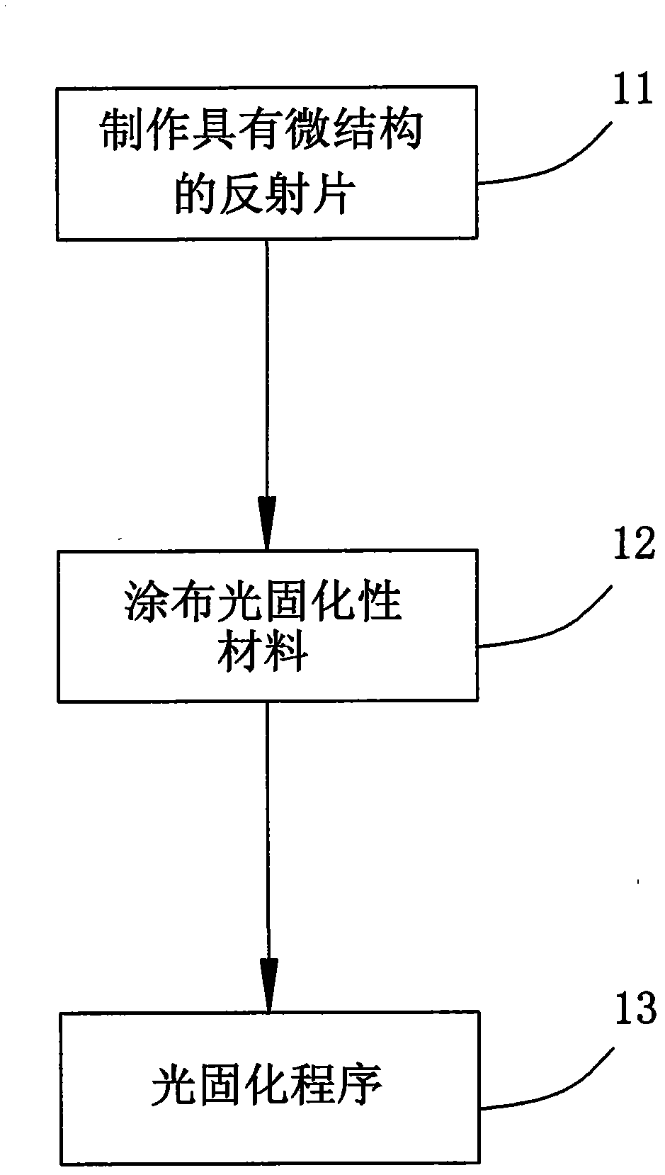
[0025] refer to figure 1 , a preferred embodiment of the manufacturing method of the light guide unit of the present invention, comprising the following steps:

[0026] Step 11: Make As figure 2 Reflective sheet 2 with microstructure 211 is shown. The reflector 2 is made of foamed polyethylene terephthalate (MCPET), and has a first surface 21 formed with a plurality of microstructures 211 and a second surface opposite to the first surface 21 twenty two. In this embodiment, the microstructure 211 of the first surface 21 is made by infrared (IR) ink process, but the present invention is not limited thereto, and other printing processes may also be used, for example: UV ink process, or non-printing process , such as: hot pressing process, injection molding and so on. That is to say, as long as the microstructure 211 is formed on the reflective shee...


PUM


Abstract

The invention relates to a manufacturing method of a light guide unit, which comprises the following steps of: (A) preparing a reflective sheet, wherein the reflective sheet is provided with a first surface and an opposite second surface and a plurality of microstructures are formed on the first surface; (B) coating a photocuring optical material on the first surface of the reflective sheet; and (C) carrying out a lighting program so as to cure the photocuring optical material to form a light guide plate. By the manufacturing method, the reflective sheet and the light guide plate are combined into the light guide unit. Therefore, the manufacturing method has the effects that the difficulty in forming the light guide plate can be reduced; the thickness of the light guide plate is also easy to control; and the wavy stripe phenomenon caused by bonding of the light guide plate and the reflective sheet can be effectively improved.

Description

technical field [0001] The invention relates to a light guide unit and a method for making a light guide element. Background technique [0002] Liquid crystal panels are widely used in today's life. Since the liquid crystal panel itself does not emit light, the backlight module is generally used to provide the light source for the liquid crystal panel. Among them, the light guide plate is a key component in the backlight module, and its function is to guide light. [0003] At present, related products using liquid crystal panels are developing toward thinning. Therefore, reducing the thickness of the light guide plate and improving the yield rate is one of the directions that various R&D factories are currently considering and working hard for. In addition, in the backlight module, in order to make the light source have better use efficiency, a reflective sheet is added at the bottom of the light guide plate, so that the light can be effectively transmitted in the light gui...

Claims


Application Information

Patent Timeline
IPC IPC(8): G02B6/00
Inventor 林忠志王铭禧黄耀德
Owner TOP VICTORY INVESTMENTS
Learn More