Air-controlled valve

A technology of controlling cavity and valve chamber, applied in valve details, valve device, valve operation/release device, etc., can solve problems such as large dead zone, and achieve the effect of simple control and small control force

Active Publication Date: 2010-03-03
오이겐자이츠아게
View PDF1 Cites 5 Cited by
  • Summary
  • Abstract
  • Description
  • Claims
  • Application Information

AI Technical Summary

Problems solved by technology

A disadvantage of this valve arrangement is that there is a relatively large dead zone, which is filled with compressed air when the valve is actuated and is finally discharged into the surrounding environment

Method used


Image

  • Air-controlled valve
  • Air-controlled valve
  • Air-controlled valve

Examples


Embodiment Construction

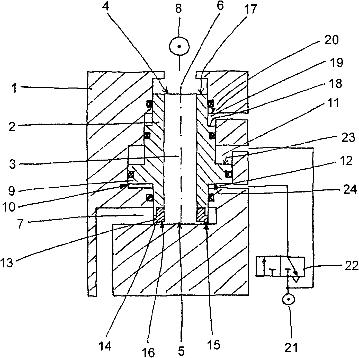
[0045] exist figure 1 A longitudinal section through the valve according to the invention is shown purely schematically. A piston 2 is embodied longitudinally displaceable in the housing 1 as an annular piston and has a centrally arranged channel 3 extending between the two end faces 4 and 5 of the piston 2 .

[0046] The upper end face 4 of the piston 2 opens into a first valve chamber 6 which is likewise formed in the housing 1 and is connected to an external pressure source 8 , for example via a pressure line 7 .

[0047] The lower end face 5 of the piston 2 opens into a second valve chamber 7 , which is connected, for example, via a connecting channel 8 also arranged in the housing 1 to a compressed air-controlled device, such as a blowing cylinder of a hollow body blower. (not shown) connection.

[0048] Furthermore, the piston 2 has in its central region a radially outwardly protruding piston ring 9 which opens into an annular chamber 10 of the housing and divides this...


PUM


Abstract

The present invention relates to a valve with a housing (1) and a piston (2), wherein the piston (2) has a channel (3) connecting the two end faces (4; 5) and a piston ring (9) which protrudes radially outward and which is arranged on the outside of the piston (2) and is disposed between the two end faces of the piston (2). A ring-shaped, axially aligned valve seal (13), the end surface (14) of which forms the closing surface (15) of the piston, is disposed on one of the two end faces (5) and, in the closed state of the piston (2), is in contact with a seating surface (15) of the correspondingvalve space (7). Furthermore, the piston (2) and the valve seal (13) are dimensioned and disposed in such a way that the active areas (16; 17) thereof are practically equalized in the open state of the piston (2) and, in the closed state, the active area (16) of the end face (5) in the region of the valve seal (13) is smaller than that of the opposite end face (4).

Description

technical field [0001] The invention relates to a valve according to the preamble of claim 1 . Background technique [0002] For the production of plastic bottles, especially PP and PET bottles, blanks or preforms are inflated into their final shape in the blowing cylinder of a hollow body blowing machine, usually in two steps. For this purpose, the blank already essentially has the finished bottle head, which is held in the tuyeres of the hollow body blower and connected to the compressed air system. By blowing compressed air through the head of the bottle, the blank is inflated and finally brought into its final shape. [0003] This inflation process is usually carried out in a two-stage method, in which the pre-blowing is carried out as the first stage at a pressure value between 2 and 20 bar through the pre-blowing valve, and subsequently in the second stage Here, final blowing, that is to say shaping the plastic bottle into its final shape, is carried out through the ...

Claims


Application Information

Patent Timeline
Patent Type & Authority Applications(China)
IPC IPC(8): F16K31/122
CPCF16K31/1226
Inventor 奥斯马尔·赖曼
Owner 오이겐자이츠아게
Why Eureka
Try Eureka