Preparation method of epoxy resin hollow micropin array

A technology of epoxy resin and microneedle array, which is applied in the direction of microneedles, chemical instruments and methods, needles, etc., to achieve the effects of small damage, easy guarantee of working effectiveness, and balanced mechanical properties

Inactive Publication Date: 2010-03-10
SHANGHAI JIAO TONG UNIV
View PDF0 Cites 16 Cited by
  • Summary
  • Abstract
  • Description
  • Claims
  • Application Information

AI Technical Summary

Problems solved by technology

The microneedles produced by this method are only solid and not hollow, and cannot be

Method used


Image

  • Preparation method of epoxy resin hollow micropin array
  • Preparation method of epoxy resin hollow micropin array

Examples


Embodiment 2

[0046] Such as figure 1 and figure 2 Shown, embodiment 2 comprises the following steps:

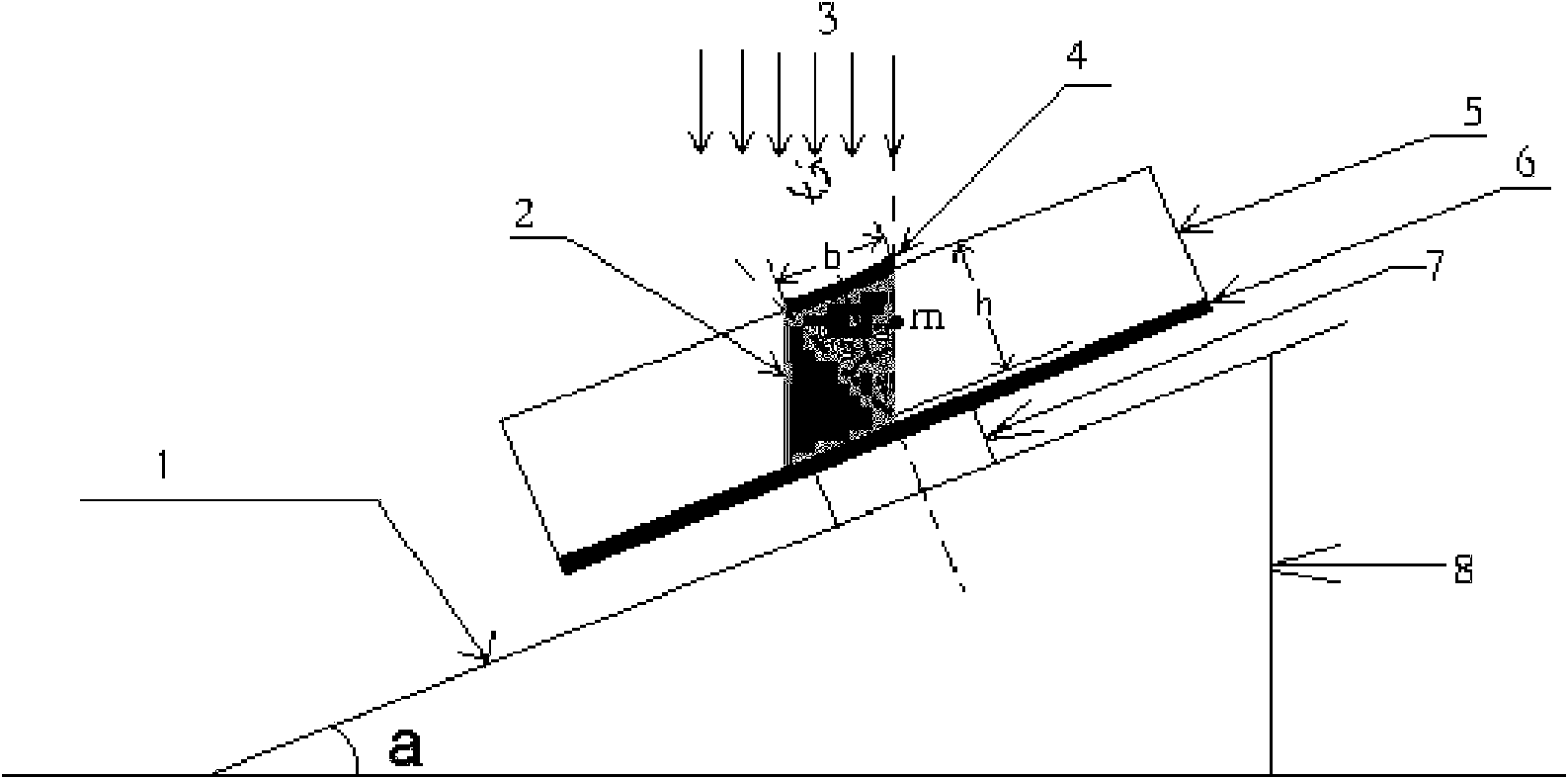
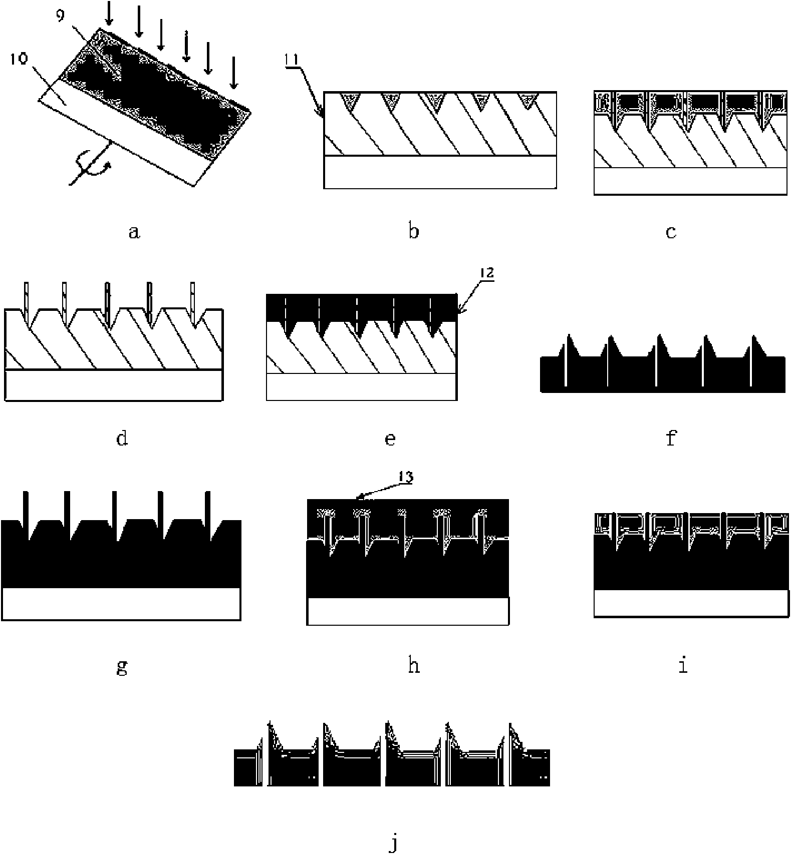
[0047] In the first step, 500 microns of SU8 photoresist was spin-coated on a 1 mm thick glass slide. Set the environment for tilt-rotation exposure: such as figure 1 As shown, adjust the inclination angle of the substrate and the reticle to be 20°, tilt the substrate and the reticle and set the apex angle of the microneedle to be twice the inclination angle of the substrate and the reticle, and then use 3.3mW / cm 2 High-power ultraviolet light, tilt and rotate the exposure for 40 minutes to the substrate and the mask, rotate the substrate and the mask at a speed of 300 rpm while exposing, and make a concave cone structure of SU8 glue, Such as figure 2 As shown in a, among them: 9 is the SU8 glue that has not been exposed to light, and 10 is the glass substrate. The concave cone structure obtained after tilt-rotation exposure is as follows figure 2 As shown in b, among them: 11 is...

Embodiment 3

[0062] Such as figure 1 and figure 2 Shown, embodiment 3 comprises the following steps:

[0063] In the first step, 500 microns of SU8 photoresist was spin-coated on a 1 mm thick glass slide. Set the environment for tilt-rotation exposure: such as figure 1 As shown, adjust the inclination angle of the substrate and the reticle to be 24°, tilt the substrate and the reticle and set the apex angle of the microneedle to twice the inclination angle of the substrate and the reticle, and then use 3.6mW / cm 2 High-power ultraviolet light, tilt and rotate the exposure for 30 minutes on the substrate and the reticle, rotate the substrate and the reticle at a speed of 300 rpm while exposing, and make a concave cone structure of SU8 glue, Such as figure 2 As shown in a, among them: 9 is the SU8 glue that has not been exposed to light, and 10 is the glass substrate. The concave cone structure obtained after tilt-rotation exposure is as follows figure 2 As shown in b, among them: 11...


PUM

PropertyMeasurementUnit
Thicknessaaaaaaaaaa
Diameteraaaaaaaaaa
Diameteraaaaaaaaaa

Abstract

The invention relates to a preparation method of an epoxy resin hollow micropin array, belonging to the technical field of a microelectronic mechanical system. The preparation method adopts the methodof organically combining inclined rotation and the traditional photoetching to prepare an SU-8 three-dimensional microstructure, obtains a bracket inclined angle of 0 to 90 degrees by adjusting the height of the bracket, then places a motor on a horizontal base plate, drives a substrate adhered thereon to rotate freely by the motor, controls rotating speed by externally applying direct current voltage on the motor, fills polydimethylsiloxane into a mold with the SU-8 three-dimensional microstructure, obtains a hollow micropin array mold after demolding, refills polydimethylsiloxane after sputtering metallic chromium-copper on the hollow micropin array for compounding, obtains a hollow micropin array mold after demolding, fills epoxy resin on the mold, demolds after grinding the bottom part into polydimethylsiloxane, and obtains the epoxy resin hollow micropin array. The prepared micropin has smooth taper shape, has better tip end and has little injury to the skin when in work.

Description

technical field [0001] The invention relates to a preparation method in the technical field of micro-electromechanical systems, in particular to a preparation method of an epoxy resin hollow microneedle array. Background technique [0002] Hollow microneedles have a special role as a carrier for microfluidic biomedical applications. On the one hand, they can reduce the pain during sampling or drug delivery. On the other hand, they have the advantages of micro-sampling, micro-volume, slow-release, and precise drug delivery. It is one of the key technologies with great application potential in the field of biomedicine. The concept of microneedles was proposed in the 1970s. But it wasn't first tested in a laboratory until the 1990s. The initial microneedles were developed to solve the pain caused by daily injections for diabetics. Because the traditional mechanical manufacturing method is not only difficult to manufacture needles with a diameter of less than 300 μm, it is al...

Claims


Application Information

Patent Timeline
IPC IPC(8): A61M37/00A61B10/00B81C5/00
CPCA61M37/0015A61M2037/003A61M2037/0053
Inventor 蒋宏民朱军曹莹杨君陈翔
Owner SHANGHAI JIAO TONG UNIV
Why Eureka
Try Eureka