Method for constructing bistatic linear-array three-dimensional imaging synthetic aperture radar system

A synthetic aperture radar and linear array technology, which is used in radio wave measurement systems, radio wave reflection/re-radiation, utilization of re-radiation, etc. Problems such as the small amount of calculation of the phase center echo data

Active Publication Date: 2010-03-10
四川电子科技大学教育发展基金会
View PDF0 Cites 14 Cited by
  • Summary
  • Abstract
  • Description
  • Claims
  • Application Information

AI Technical Summary

Problems solved by technology

The working model of the system is attached figure 1 It can be seen from the model of the system that since the receiving platform of the system moves along the set curve trajectory, the low control precision of the antenna phase center and the significant error of the moving platform are still difficult to overcome, and it is also difficult to Realize the arbitrary path flight of the receiving trajectory, but because it inherits the advantages of the bistatic synthetic aperture radar, such as B.D.Rigling and R.L.Moses, "Flightpath strategies for 3-D scene reconstruction from bistatic SAR" IEEproceedings Radar Sonar Navig., vol.151 No 3.pp.149-157, June.2004. Mentioned: anti-stealth, rich scattering information of the target, increased radar cross-sectional area, etc. This system has also become a research hotspot in the current 3D SAR
[0005]The above-mentioned system essentially has low control precision of the antenna phase center trajectory, difficulty in obtaining an arbitrarily set flight path, high power consumption, and a large amount of data processing , Coupling between array elements is inevitable, etc.
According to the invention, there is currently no complete three-dimensional SAR system, which has the advantages of high control precision of the antenna phase center, the ability to obtain echoes under any curved trajectory, and the calculation amount of echo data is small, etc.

Method used


Image

  • Method for constructing bistatic linear-array three-dimensional imaging synthetic aperture radar system
  • Method for constructing bistatic linear-array three-dimensional imaging synthetic aperture radar system
  • Method for constructing bistatic linear-array three-dimensional imaging synthetic aperture radar system

Examples


Embodiment Construction

[0080] The present invention mainly uses the simulation experiment method to verify the feasibility of the system model, and all steps and conclusions are verified correctly on VC++ and MATLAB7.0. The specific implementation steps are as follows:

[0081] Step 1: Launch System Construction

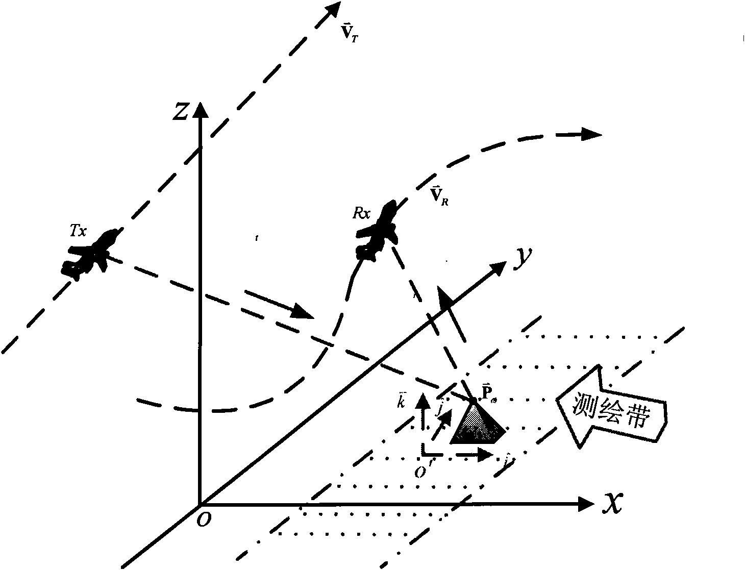
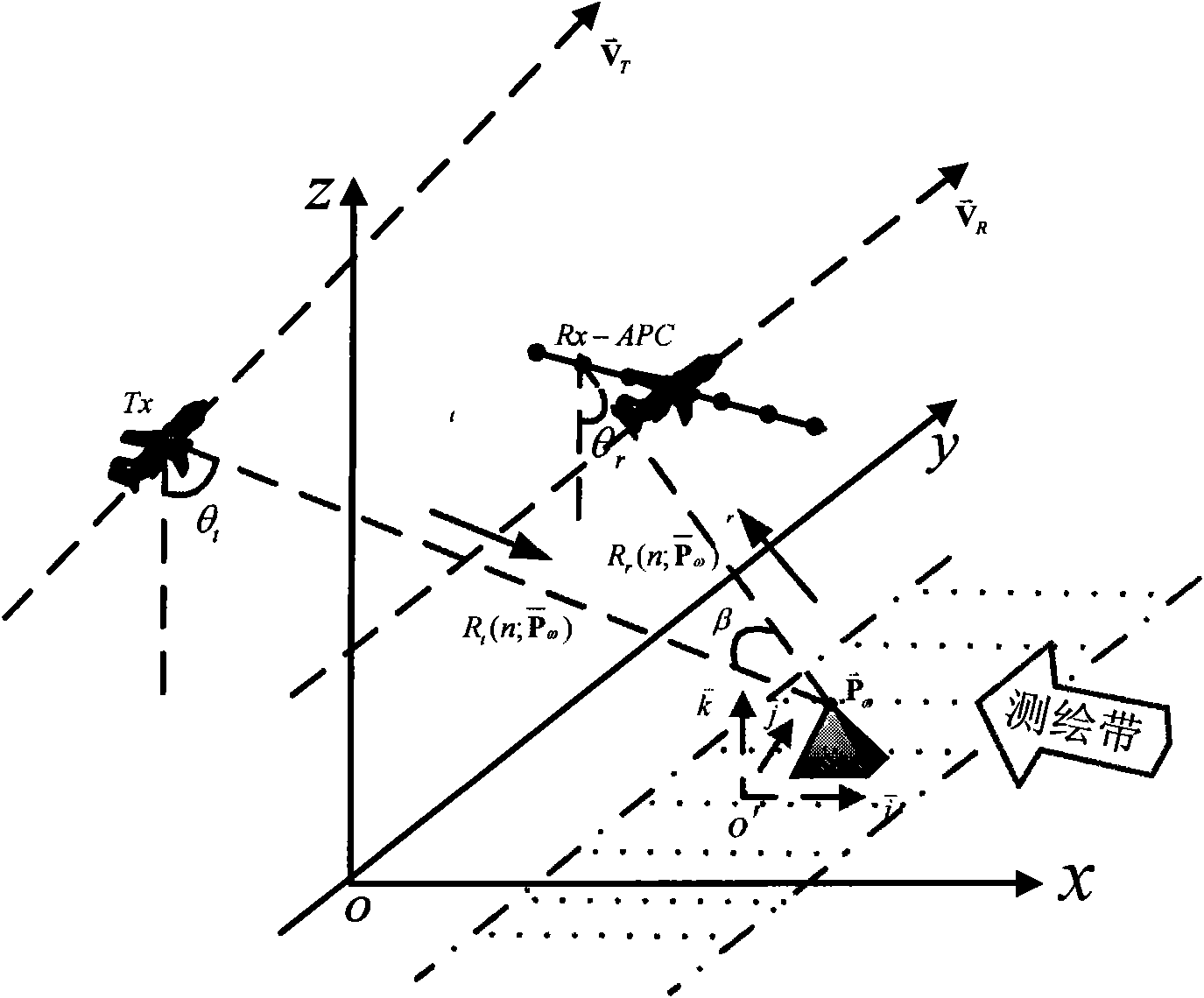
[0082] The launch system of the two-station linear array 3D synthetic aperture radar system is to place the transmitter on the launch platform to form the launch system. The launch bandwidth of the transmitter is 750MHz, the pulse width is 0.1E-6s, the azimuth beam angle is 2 degrees, and the horizontal beam angle It is a 30-degree chirp signal, and the chirp signal emitted by the transmitter is transmitted at a carrier frequency of 10GHz at a pulse repetition frequency of 1200Hz. The launch platform flies at a constant vector velocity [0 100 0], the velocity unit is m / s, and its initial flight altitude is 2500m;

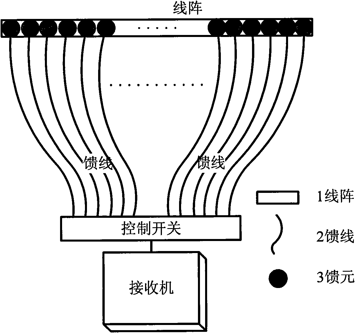
[0083] Step 2: Line Array Receiver Construction

[0084] The linear arra...


PUM


Abstract

The invention provides a method for constructing a bistatic linear-array three-dimensional synthetic aperture radar system. The method utilizes a principle of a synthetic aperture radar, combines thecharacteristics of high antenna phase center control accuracy in a linear-array three-dimensional synthetic aperture radar and anti-stealth, rich target scattering information and increased radar cross sectional area in the current bistatic synthetic aperture radar system, utilizes the characteristic of combining the bistatic synthetic aperture radar system with a linear-array system, and uses a single-feedback motivational pattern to reduce the power consumption and hardware complexity greatly, overcome a range ambiguity effect and realize three-dimensional imaging of an observed scene. The method realizes three-dimensional imaging of the bistatic linear-array synthetic aperture radar with a small data processing quantity with relatively low hardware cost. The method can be widely appliedin the fields such as synthetic aperture radar imaging, earth remote sensing and geological mapping.

Description

technical field [0001] The invention belongs to the technical field of radar, and in particular relates to the technical field of synthetic aperture radar (SAR). Background technique [0002] Three-dimensional imaging is an important feature that distinguishes three-dimensional imaging synthetic aperture radar (SAR) from other remote sensing imaging systems. Due to its wide surveying and mapping range, all-weather and all-weather characteristics, it has broad applications in terrain surveying and mapping, environmental detection, disaster forecasting, etc. prospect. [0003] The current related systems of 3D SAR technology mainly include Interferometric SAR (InSAR) system, Curve SAR (CSAR) system and Linear Array SAR (LASAR) system. The interferometric SAR system is a three-dimensional SAR system of digital elevation obtained by interfering two or more observation data of the same observation area obtained by the antenna at different angles. cannot provide accurate 3D reco...

Claims


Application Information

Patent Timeline
Patent Type & Authority Applications(China)
IPC IPC(8): G01S13/90
Inventor 张晓玲王银波师君李伟华
Owner 四川电子科技大学教育发展基金会
Why Eureka
Try Eureka