Method for calibrating zeroing of servo mechanism

A zero-correction and servo-machine technology, applied in the field of servo machines, can solve the problems of increasing the number of components, difficult assembly of the servo machine 1, and increasing manufacturing costs, and achieves the effect of simplifying the structure.

Inactive Publication Date: 2010-03-10
MICRO-STAR INTERNATIONAL
View PDF0 Cites 20 Cited by
  • Summary
  • Abstract
  • Description
  • Claims
  • Application Information

AI Technical Summary

Problems solved by technology

[0005] However, in the aforementioned zero-return correction method, the detection device 4 must be used to judge whether the moving part 3 of the servo machine 1 has displaced to the limit position, so as to calculate the maximum movement amount of the servo machine 1
The arrangement of the det

Method used


Image

  • Method for calibrating zeroing of servo mechanism
  • Method for calibrating zeroing of servo mechanism
  • Method for calibrating zeroing of servo mechanism

Examples


Embodiment Construction

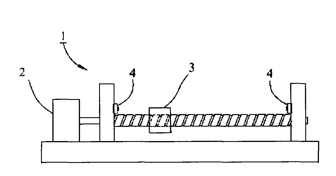
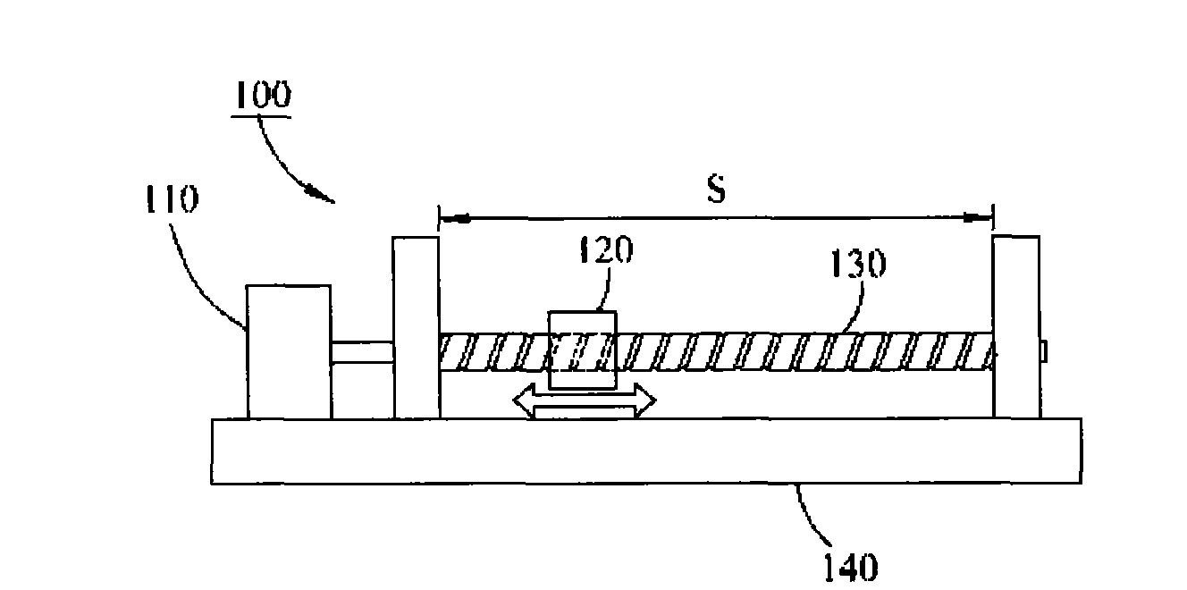
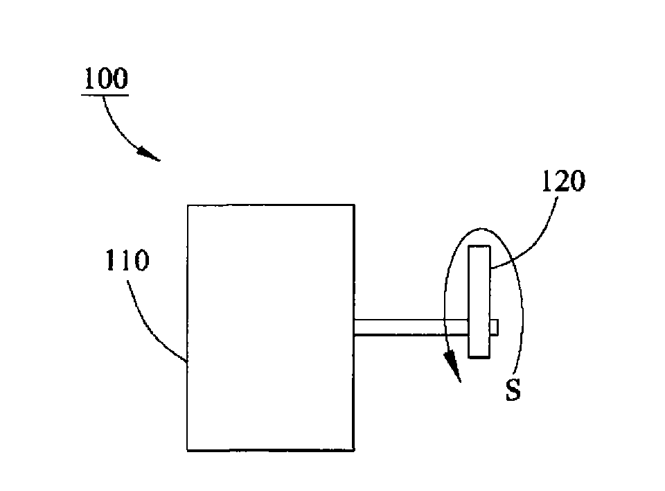
[0046] see figure 2 and image 3 As shown, it is a zero-return calibration method of the servo machine disclosed in the embodiment of the present invention, which is used to obtain the relationship between the movement amount of the servo motor 110 and the movement amount of the moving part 120 to achieve the calibration operation of the servo machine 100 .

[0047] refer to figure 2 and image 3 As shown, it is a schematic diagram of two different forms of the servo machine 100 . Each servo machine 100 includes a servo motor 110 and a moving part 120 . The servo motor 110 is used to drive the moving part 120 to move along the moving path S. As shown in FIG. The motion path S can be a linear path or a rotational angle. When the motion path S is a linear path, the output shaft of the servo motor 110 is connected to the moving part 120 with a transmission device 130 such as a screw or a belt, and the rotational output of the servo motor 110 is converted into a linear outp...


PUM


Abstract

The invention relates to a method for calibrating the zeroing of a servo mechanism, which comprises the following steps: driving a servo motor in a low rotation speed mode to drive a moving part to move to a first extreme position and a second extreme position respectively; in the moving process of the moving part, continuing to detect whether the motor control energy of the servo motor exceeds afirst threshold value or a second threshold value; acquiring a motor coordinate value corresponding to the first or second extreme position when the motor control energy is increased to exceed the first threshold value or the second threshold value when the moving part reaches the first or second extreme position; and finally, calculating a conversion function of the motor coordinate and the actual coordinate by utilizing an actual coordinate value of the first extreme position, an actual coordinate value of the second extreme position, the motor coordinate value corresponding to the first extreme position and the motor coordinate value corresponding to the second extreme position. The method can simplify the structure of the servo mechanism and avoiding the use of an additional detectiondevice for determining whether the moving part reaches the extreme position.

Description

technical field [0001] The invention relates to a servo machine, in particular to a zero-returning correction method for the servo machine without additional detection devices. Background technique [0002] refer to figure 1 As shown, the servo machine 1 includes a servo motor 2 and a moving part 3 driven by the servo motor 2 . The servo machine 1 must be calibrated so that each output of the servo motor 2 can drive the moving part 3 to a predetermined position or rotate to a predetermined angle. [0003] Regardless of whether the servo machine 1 is a linear output or a rotary output, the moving part 3 will have two limit positions, which are located at both ends of the motion path. If the movement path of the moving part 3 is a linear path, the maximum distance that the moving part 3 can move is between the two limit positions. If the moving path of the moving part 3 is rotation, then the two limit positions are the maximum angles of forward rotation and reverse rotation...

Claims


Application Information

Patent Timeline
IPC IPC(8): G05B19/4062
Inventor 黎永昇洪士哲
Owner MICRO-STAR INTERNATIONAL
Why Eureka
Try Eureka