Check patentability & draft patents in minutes with Patsnap Eureka AI!

Magnetic element

A technology of magnetic components and magnetic substrates, which can be used in electrical components, impedance networks, inductors, etc., to solve problems such as filter bandwidth or inductance space limitation and limitation.

Inactive Publication Date: 2010-03-10
DELTA ELECTRONICS INC
View PDF0 Cites 2 Cited by
  • Summary
  • Abstract
  • Description
  • Claims
  • Application Information

AI Technical Summary

Problems solved by technology

The bandwidth or inductance of the filters currently used are severely limited due to space constraints

Method used


Image

  • Magnetic element
  • Magnetic element
  • Magnetic element

Examples


Embodiment Construction

[0045] A magnetic element according to various embodiments of the present invention will be described below with reference to related drawings.

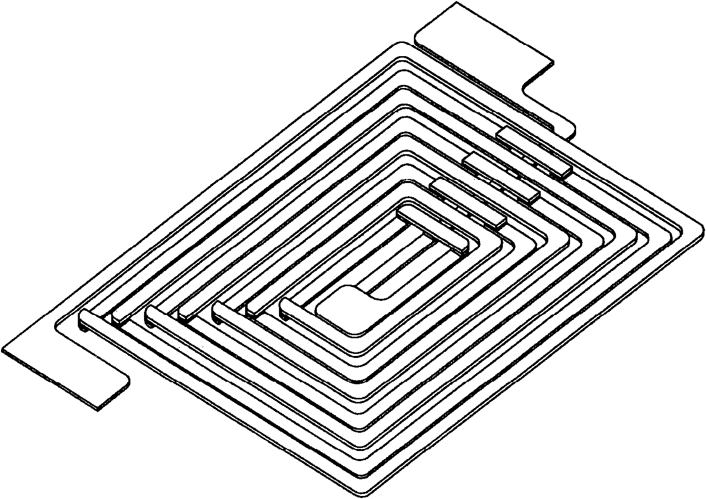
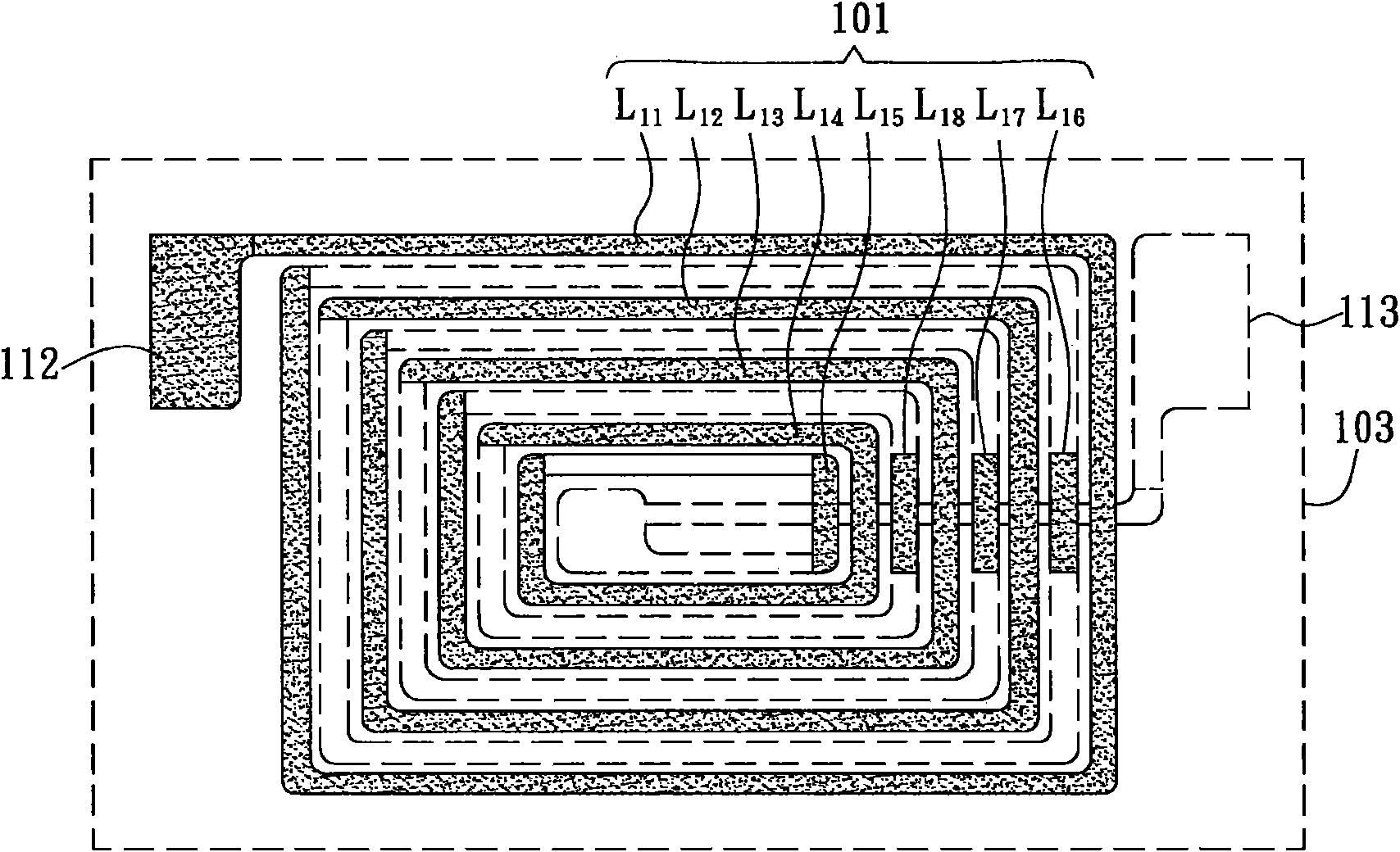
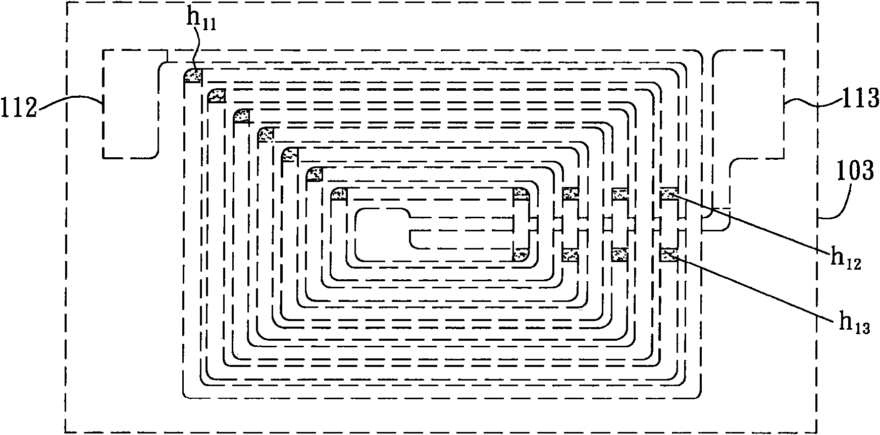
[0046] Please also refer to Figure 1A to Figure 1D as shown, Figure 1A It is a schematic diagram of wiring of one coil group of the magnetic element of the present invention. The magnetic element of the present invention includes two coil groups, and each coil group is as Figure 1A The structure shown is composed of a first coil 101 and a second coil 102 . Figure 1B for Figure 1A The wiring diagram of the first coil in Figure 1D for Figure 1A The wiring diagram of the second coil in Figure 1C It is a schematic diagram of the configuration of the conductive pillars connecting the first coil and the second coil.

[0047] The first coil 101 has a plurality of first metal wire segments L11-L18, and the second coil 102 has a plurality of second metal wire segments L21-L28. Of course, the number of the first metal line segment a...


PUM

PropertyMeasurementUnit
Thicknessaaaaaaaaaa
Widthaaaaaaaaaa
Thicknessaaaaaaaaaa

Abstract

The invention provides a magnetic element, which comprises two coil assemblies, wherein each coil assembly comprises a first coil having a plurality of first metal segments, a second coil having a plurality of second metal segments, and at least one conductive post connected between the first and second coils. The magnetic element also comprises an encapsulation body, and the two coil assemblies are encapsulated in the encapsulation body.

Description

technical field [0001] The present invention relates to a magnetic component, in particular to a filter capable of eliminating common mode noise. Background technique [0002] In recent years, the application of power electronic circuits has become more and more widespread, and such circuits are usually operated at high frequency switching, so they are prone to generate Electro Magnetic Interference (EMI). These high-frequency noises will interfere with the normal operation of other electrical equipment through electromagnetic radiation or power line conduction. Among them, the conducted EMI can be divided into Differential Mode (DM) noise and Common Mode (CM) noise according to the difference of the noise current transmission path. [0003] In order to effectively eliminate electromagnetic interference, corresponding filters are generally installed in electronic devices according to the type of noise to be eliminated. For example, in order to eliminate common mode noise, ...

Claims


Application Information

Patent Timeline
IPC IPC(8): H01F17/00H03H1/02
Inventor 李政鸿张志宏黄逸鸿
Owner DELTA ELECTRONICS INC
Features
  • R&D
  • Intellectual Property
  • Life Sciences
  • Materials
  • Tech Scout
  • Unparalleled Data Quality
  • Higher Quality Content
  • 60% Fewer Hallucinations
Learn More