Regulation circuit and regulation method for light-emitting diode

A technology of light-emitting diodes and regulating circuits, which is applied to the layout of electric lamp circuits, light sources, electric light sources, etc., can solve problems such as insufficient heat dissipation, thermal burnout of light-emitting diodes, and poor heat dissipation efficiency, so as to reduce continuous accumulation and facilitate manufacturing and assembly Effect

Inactive Publication Date: 2010-03-10
ZIPPY TECH
View PDF0 Cites 3 Cited by
  • Summary
  • Abstract
  • Description
  • Claims
  • Application Information

AI Technical Summary

Problems solved by technology

However, in the process of heat transfer, the light-emitting diodes that work under high-current conditions often accumulate heat energy due to poor heat dissipation efficiency. The accumulated position is also called a hot spot. The generation of hot spots may cause the light-emitting diode to generate heat danger of burning
Although it is generally possible to solve the problem of insufficient heat dissipation by installing cooling fins or even installing a cooling fan outside the overall LED module, as the power of LEDs gradually increases, the need to expand the combination of components and increase the occupied volume , will inevitably affect the appearance and assembly process of LED products, and is not a proper solution

Method used


Image

  • Regulation circuit and regulation method for light-emitting diode
  • Regulation circuit and regulation method for light-emitting diode
  • Regulation circuit and regulation method for light-emitting diode

Examples


Embodiment Construction

[0021] Relevant detailed description and technical content of the present invention, cooperate schematic diagram to illustrate as follows now:

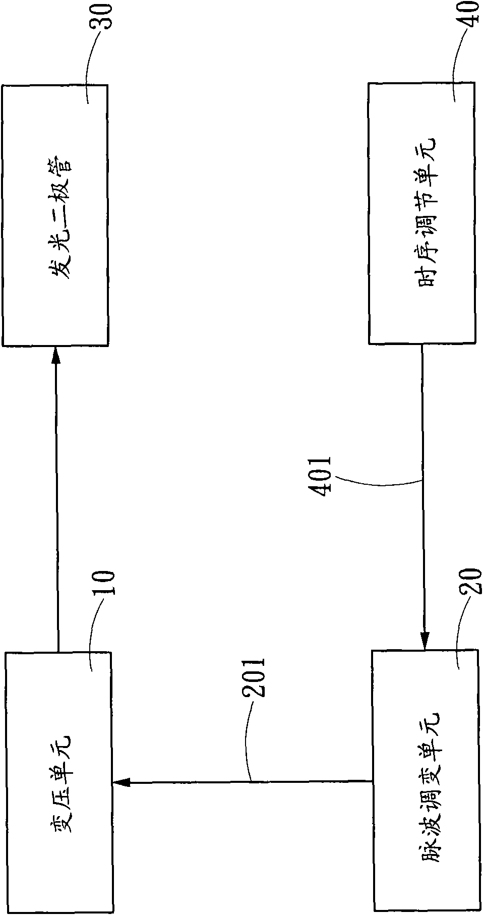
[0022] see figure 1 As shown, it is a schematic circuit block diagram of a preferred embodiment of the present invention, as shown in the figure: the present invention is a light-emitting diode adjustment circuit, which has a transformer that obtains DC power and provides a constant current to drive at least one light-emitting diode 30 The unit 10 and a pulse modulation unit 20 generate a driving signal 201 to control the transforming unit 10 . The pulse modulation unit 20 is connected to a timing adjustment unit 40 for receiving an adjustment signal 401 generated by the timing adjustment unit 40 .

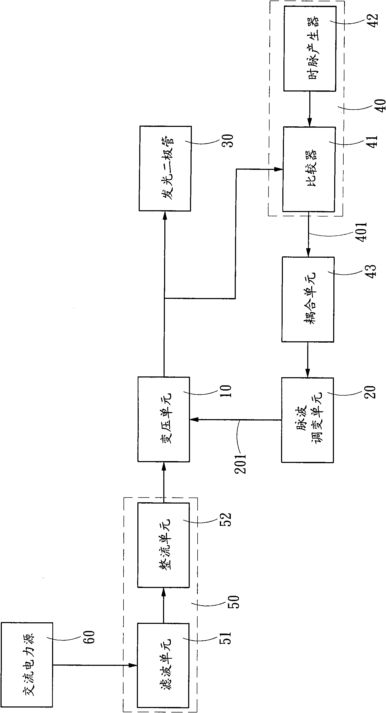
[0023] see figure 2 As shown, it is a schematic circuit block diagram of another embodiment of the present invention, as shown in the figure: the transformer unit 10 is electrically connected to a rectification and filtering circuit 5...


PUM


Abstract

The invention discloses a regulation circuit and a regulation method for a light-emitting diode. The regulation circuit is provided with a variable voltage unit for acquiring direct current power andproviding constant current to drive at least one light-emitting diode, and a pulse modulation unit for generating a driving signal to control the variable voltage unit. The driving signal of the pulsemodulation unit has an operation cycle, the driving signal under the operation cycle drives the variable voltage unit to output normal operation power, while the pulse modulation unit is connected with a time sequence regulation unit which generates a regulation signal to be sent to the pulse modulation unit to modulate a dormancy cycle added into the operation cycle of the driving signal, and the driving signal under the dormancy cycle reduces the power through which the variable voltage unit drives the light-emitting diode. Therefore, the variable voltage unit regulates the power output tothe light-emitting diode according to the alternate control of the operation cycle and the dormancy cycle of the driving signal to avoid the light-emitting diode emitting heat continuously so as to reduce the accumulation of heat energy.

Description

technical field [0001] The invention relates to a regulating circuit and a regulating method of an electronic device, in particular to a regulating circuit and a regulating method of a light-emitting diode. Background technique [0002] Light Emitting Diodes (LEDs) are widely used in daily life due to their advantages over traditional lighting equipment such as high efficiency, long life, and unbreakable properties. However, the light-emitting diodes are driven to emit light by receiving high current from the front-end DC power supply source. The high current output by the DC power supply source is in a certain current mode, such as Image 6 As shown, the light-emitting diode will generate a lot of heat in addition to light after continuously receiving the fixed high current. The accumulation of a large amount of heat energy may lead to overheating and lead to the failure of LEDs. The phosphors used in white LEDs may also decline due to heat and change the color of light pro...

Claims


Application Information

Patent Timeline
Patent Type & Authority Applications(China)
IPC IPC(8): H05B37/02
CPCY02B20/42Y02B20/40
Inventor 钟金标
Owner ZIPPY TECH
Why Eureka
Try Eureka