Non-pneumatic tire and its manufacturing method

A technology of tires and annular parts, applied in non-pneumatic tires, tire parts, vehicle parts, etc., can solve the problems of heavy and firm tires, deterioration of load-supporting performance or durability, and lack of excellent performance of pneumatic tires. The effect of stress concentration and durability improvement

Inactive Publication Date: 2011-11-30
TOYO TIRE & RUBBER CO LTD
View PDF2 Cites 0 Cited by
  • Summary
  • Abstract
  • Description
  • Claims
  • Application Information

AI Technical Summary

Problems solved by technology

[0004] As conventional non-pneumatic tires, there are solid tires, spring tires, soft-core tires, etc., but they do not have the excellent performance of pneumatic tires
For example, although solid tires and soft-core tires support loads through the compression of the ground part, such tires are bulky and strong, and do not have the impact absorption capacity like pneumatic tires
In addition, in non-pneumatic tires, the cushioning performance can also be improved by increasing elasticity, but there is a problem that the load supporting performance and durability of pneumatic tires deteriorate

Method used


Image

  • Non-pneumatic tire and its manufacturing method
  • Non-pneumatic tire and its manufacturing method
  • Non-pneumatic tire and its manufacturing method

Examples


Embodiment approach

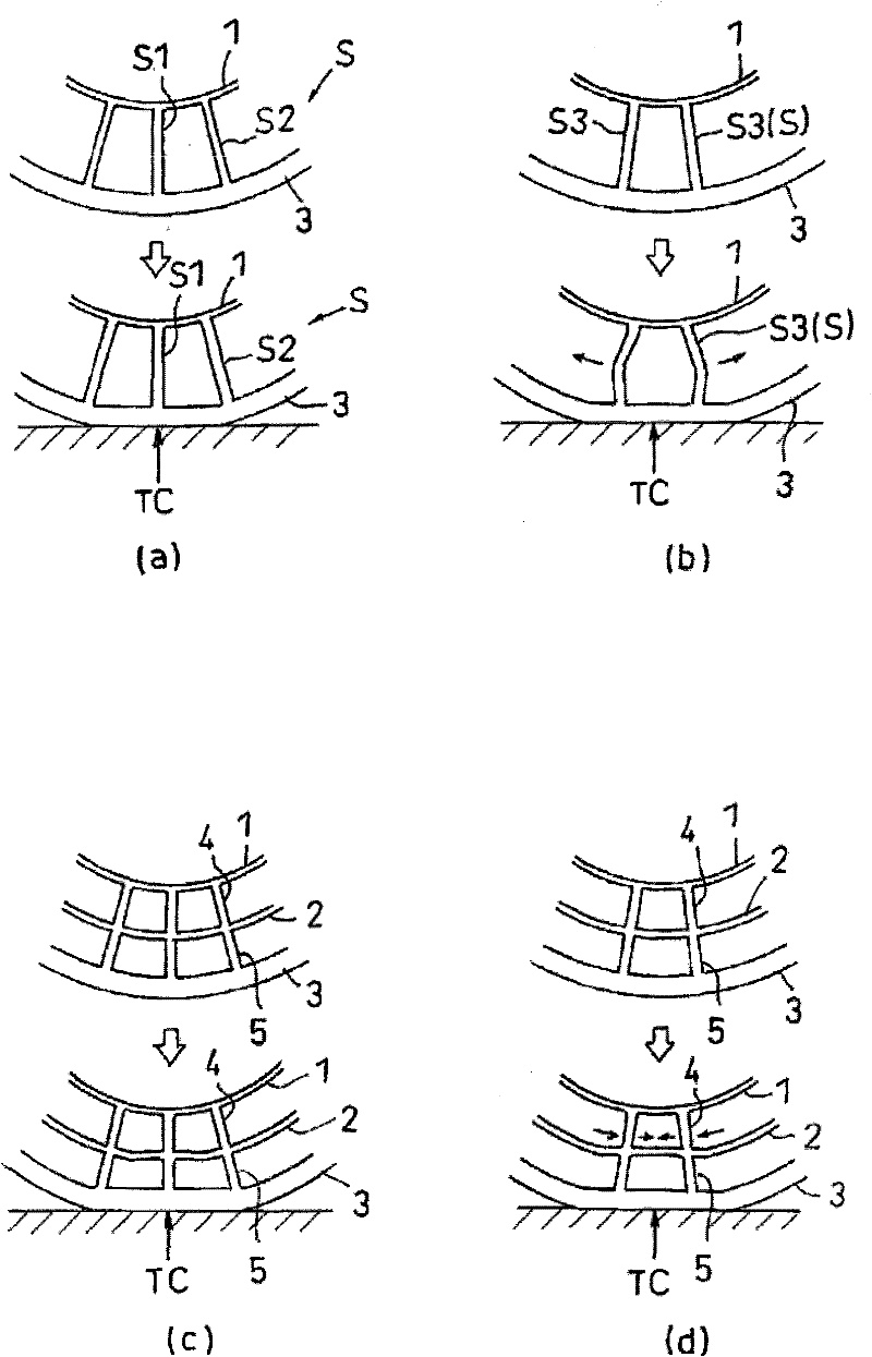
[0096] (1) In the above-mentioned embodiment, the example in which the flat inner connection part and the outer connection part are arranged in parallel in the axial direction is shown, but as Figure 5 As shown in a to d, the shapes and formation directions of the inner connecting portion and the outer connecting portion can take various shapes.

[0097] For example, if Figure 5 As shown in a, the arrangement direction of the outer connecting portion 5 (and the same for the inner connecting portion) may be inclined from the direction of the axis O.

[0098] and, if Figure 5 As shown in b, the outer connecting portion 5 (the inner connecting portion is also the same) may be in the shape of a curved flat plate.

[0099] and, if Figure 5 As shown in c, the outer connection part 5 (the inner connection part is also the same) can also be in the shape of a flat plate with a rim 5a.

[0100] and, if Figure 5 As shown in d, a plurality of outer connection portions 5 may be f...

Embodiment

[0107] Hereinafter, Examples etc. which concretely show the structure and effect of this invention are demonstrated. In addition, the evaluation items in Examples etc. were measured as follows.

[0108] (1) Maximum ground pressure

[0109] It refers to the case where the outer end point of the outer wheel bar (or wheel bar) is on the grounding center and the center position of the outer end point of the adjacent outer wheel bar (or wheel bar) is on the grounding center when bearing a longitudinal load of 2000N The amount of averaging the maximum ground pressure in each ground plane in the case of , is represented by an index when comparative example 1 is set to 100. The smaller the value, the better.

[0110] (2) Maximum ground pressure difference

[0111] It refers to the case where the outer end point of the outer wheel bar (or wheel bar) is on the grounding center and the center position of the outer end point of the adjacent outer wheel bar (or wheel bar) is on the grou...

Embodiment 1

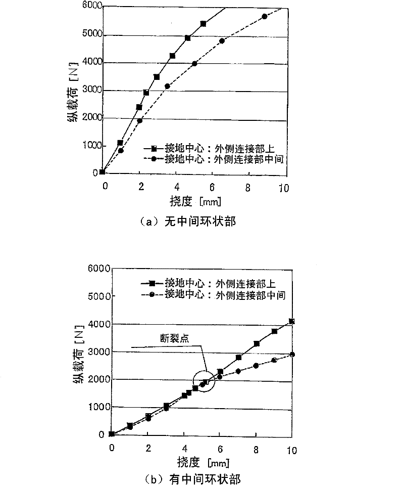
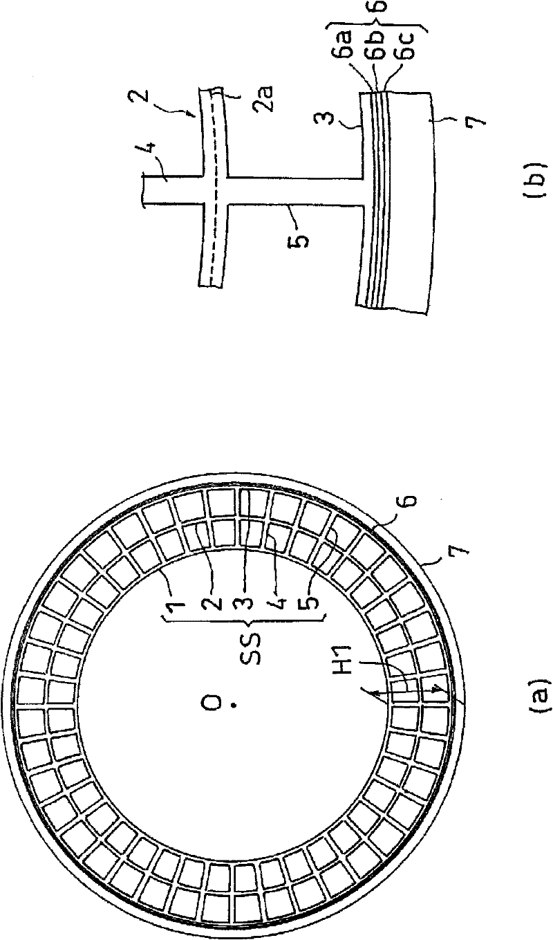
[0126] According to the dimensions and physical properties shown in Table 1, a support structure having an inner ring, an intermediate ring, an outer ring, and an inner wheel bar (upright in the radial direction) and an outer wheel bar (upright in the radial direction) connecting each ring was manufactured, A non-pneumatic tire having two layers of reinforcing layers and tire rubber provided on its outer periphery was produced, and the above-mentioned performance was evaluated. The results are combined and shown in Table 1. Also, the results of the rigidity variation test are shown in Figure 6 middle.

[0127] And, the molding of support structure is carried out as follows, use the mold that has the space part corresponding to support structure, on the part corresponding to the intermediate ring of this space part, dispose the glass fiber material of mesh shape shown in Table 1, after that Fill the entire space of the mold with a raw material solution of an elastic material...


PUM


Abstract

The present invention relates to a non-pneumatic tire having a support structure for supporting loads from a vehicle. The support structure (SS) has: an inner annular portion (1), and an intermediate annular portion ( 2), an outer annular portion (3) arranged in a concentric circle on its outer side, a plurality of inner connecting portions (4) that connect the inner annular portion (1) and the middle annular portion (2) and are independent in the circumferential direction ), connecting the outer annular portion (3) and the intermediate annular portion (2) and a plurality of outer connecting portions (5) that are independent in the circumferential direction.

Description

technical field [0001] The present invention relates to a non-pneumatic tire having a support structure for supporting loads from a vehicle as a structural component of the tire and a method of manufacturing the same, more particularly to a non-pneumatic tire that can be used instead of a pneumatic tire. Background technique [0002] Pneumatic tires have the functions of supporting loads, absorbing impacts from the ground, and transmitting power (acceleration, stopping, and direction change), so they are used in various vehicles, especially bicycles, motorcycles, cars, and trucks . [0003] In particular, these capabilities have greatly contributed to the development of automobiles and other motorized vehicles. In addition, the shock absorbing ability of the pneumatic tire can also be used in other applications such as a cart for transporting medical equipment and electronic equipment. [0004] Conventional non-pneumatic tires include, for example, solid tires, spring tire...

Claims


Application Information

Patent Timeline
Patent Type & Authority Patents(China)
IPC IPC(8): B60C7/00B60C7/18
Inventor 岩瀬雅则瀬川政弘
Owner TOYO TIRE & RUBBER CO LTD
Why Eureka
Try Eureka