Inkjet head cleaning device

A cleaning device and inkjet head technology, applied in printing and other directions, can solve problems such as increased pressure loss, obstruction of liquid delivery, damage to liquid delivery path, etc., to achieve the effects of reduced contact area, reduced flow resistance, and reduced pressure loss

Active Publication Date: 2010-03-17
ISHII HYOKI
View PDF7 Cites 4 Cited by
  • Summary
  • Abstract
  • Description
  • Claims
  • Application Information

AI Technical Summary

Problems solved by technology

Therefore, it is necessary to make the liquid delivery path high-strength, which not only incurs an increase in manufacturing cost, but also tends to cause damage to the liquid delivery path, and increases the pressure loss to cause waste.
Therefore, although this method may be applied to liquid materials with low viscosity (such as liquid materials with a viscosity less than 5 cp), it may hinder the delivery of high-viscosity liquid materials (such as liquid materials with a viscosity above 5 cp or above 6 cp). Liquid and other fatal problems
Therefore, the structure is complicated,

Method used


Image

  • Inkjet head cleaning device
  • Inkjet head cleaning device
  • Inkjet head cleaning device

Examples


no. 1 approach

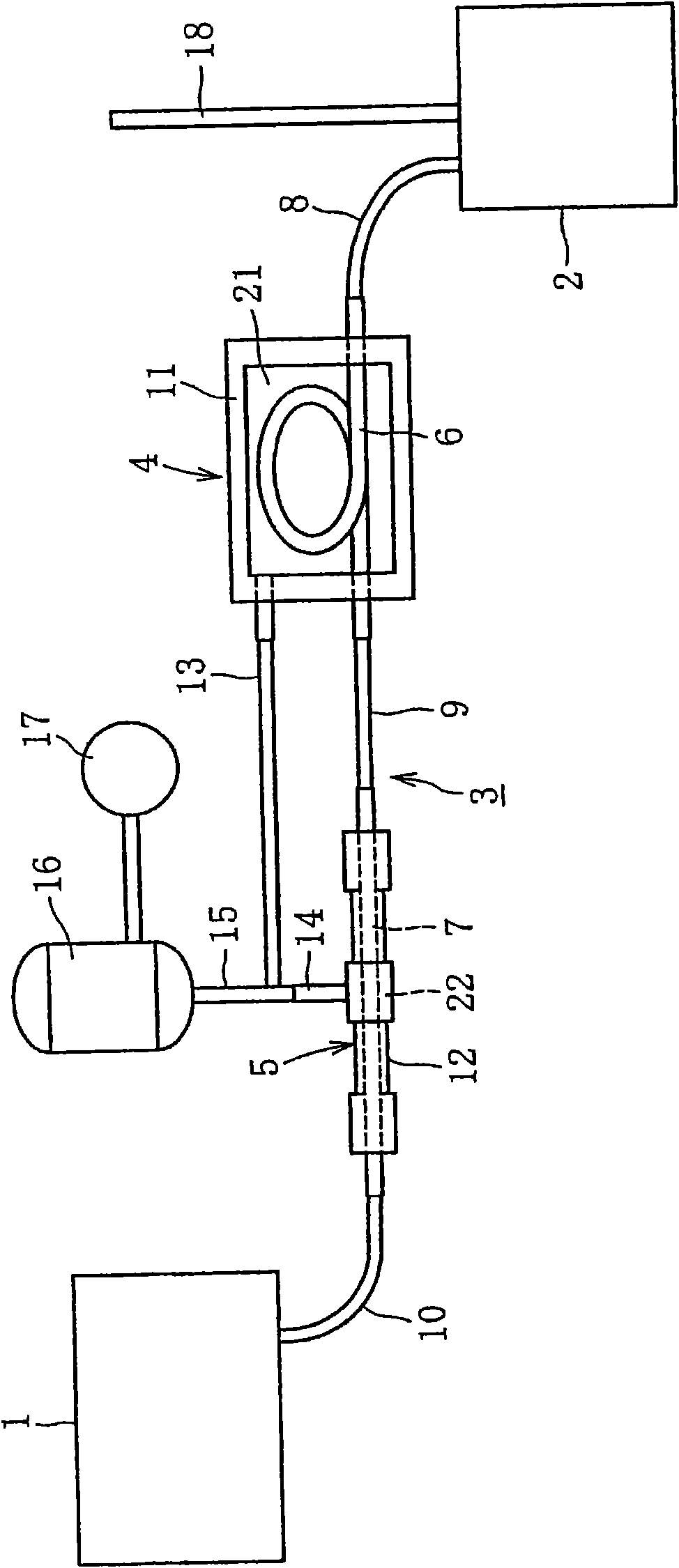
[0113] figure 1 The ink jet head liquid feeding device according to the first embodiment of the present invention is exemplified. like figure 1 As shown, in the ink jet head liquid feeding device according to the first embodiment, the ink tank 1 storing the liquid material is communicated with a common liquid feeding pipeline 2 extending in the horizontal direction at a position below the ink tank 1, and in the common liquid feeding pipe 2 The liquid feeding pipeline 2 is connected with a plurality of independent liquid feeding pipelines 3 at equal intervals. These independent liquid feeding pipes 3 extend downward from the common liquid feeding pipe 2, and the lower ends of the respective independent liquid feeding pipes 3 are respectively connected to the ink jet heads 4 (the liquid reservoirs inside thereof), and these independent liquid feeding pipes 3 are arranged in the vertical direction. On the way, degassing units 5 for degassing air bubbles such as air in the liq...

no. 2 approach

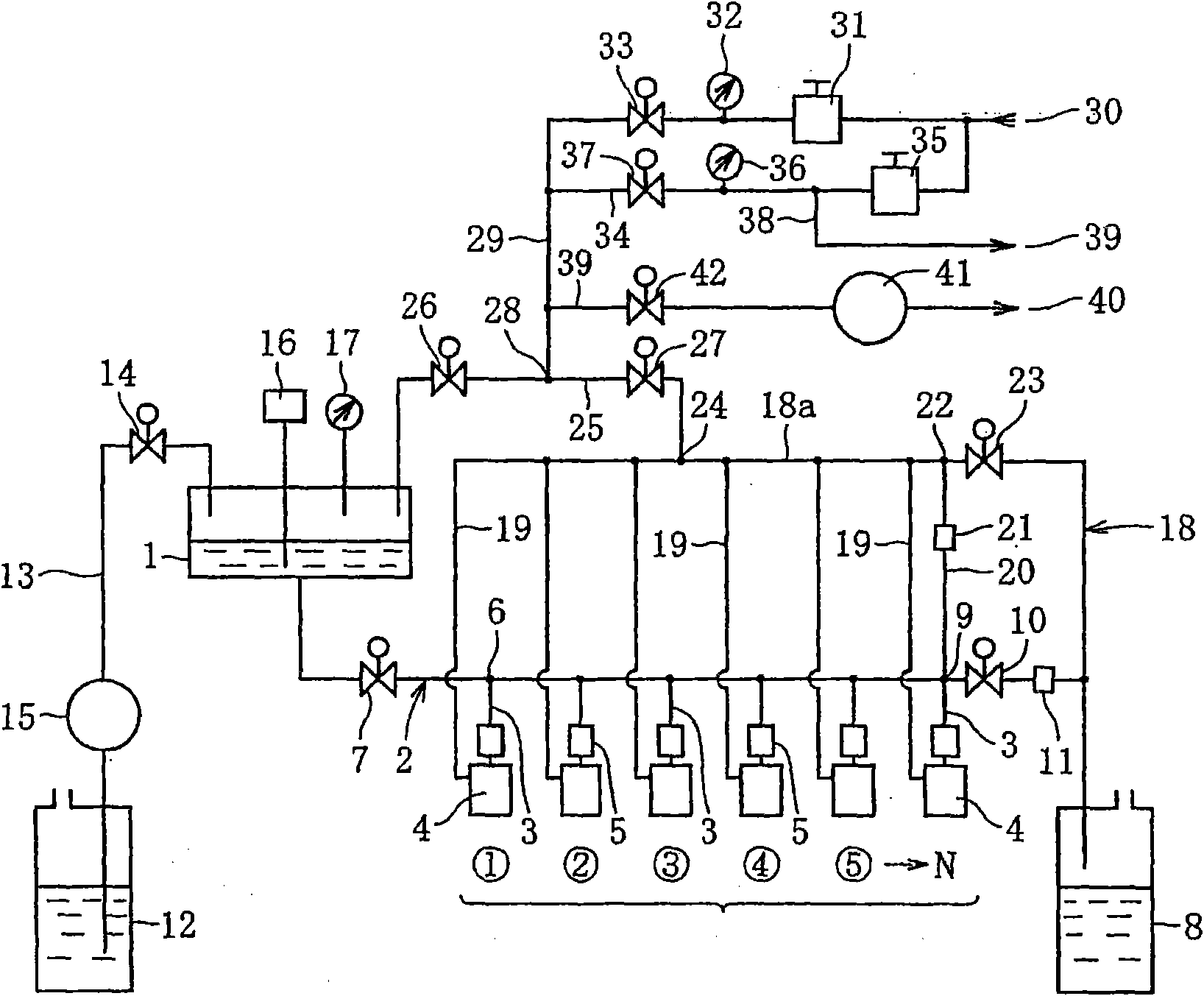
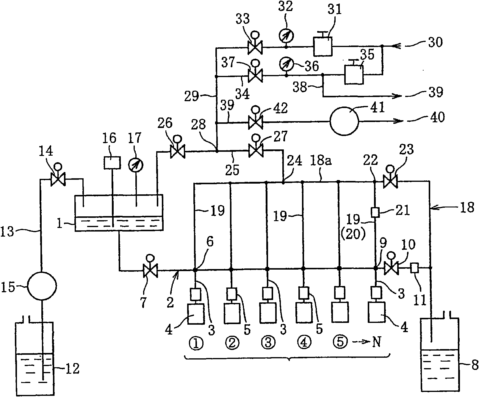
[0124] figure 2 The ink jet head liquid feeding device according to the second embodiment of the present invention is exemplified. like figure 2 As shown, the difference between the inkjet head liquid feeding device of the second embodiment and the inkjet head liquid feeding device of the above-mentioned first embodiment has two points: one is the bypass pipe from the common air diffusing pipe 18 Each lower end of each independent air-diffusing pipeline 19 extending downward from 18a is communicated with each connection part of the public liquid-feeding pipeline 2 and each independent liquid-feeding pipeline 3; the second is that the independent air-diffusing pipeline 19 at the most downstream end is also used as a liquid-feeding and air-diffusing pipe. Road 20. The other components are the same as those of the inkjet head liquid feeding device of the first embodiment described above, and therefore the same reference numerals are used for the common components in both of t...

no. 3 approach

[0128] Figure 3 to Figure 5 The ink jet head liquid feeding device according to the third embodiment of the present invention is exemplified. like image 3 As shown, the inkjet head liquid feeding device of the third embodiment has a liquid feeding path 3 for feeding the liquid material from the ink reservoir 1 storing the liquid material to the inkjet head 2 (internal liquid reservoir), The first degassing unit 4 and the second degassing unit 5 are provided at two places in the middle of the liquid feeding path 3 . The liquid supply path 3 is composed of two degassing pipes (hereinafter referred to as first and second degassing pipes 6 and 7) made of synthetic resin having air permeability and having a single internal flow path, and two degassing pipes having no air permeability and having a single internal flow path. It is formed by connecting three liquid feeding pipes (hereinafter referred to as the first to third liquid feeding pipes 8, 9 and 10) made of metal or the l...


PUM

PropertyMeasurementUnit
Viscosityaaaaaaaaaa
Surface tensionaaaaaaaaaa
Vertical sizeaaaaaaaaaa

Abstract

The invention provides an inkjet head cleaning device that can not cause the complication of pipelines or lead gas to remain in a liquid conveying pipeline when supplying liquid material to the inkjethead, and aims at leading the hydraulic pressure of the liquid material supplied to each inkjet head to be uniform. Independent liquid conveying pipelines (3) used for supplying liquid material and respectively communicated with a plurality of inkjet heads (4) are connected with a public liquid conveying pipeline (2) that is communicated with an ink tank (1) storing the liquid material, independent gas diffuser pipelines (19), in which gas can flow, are connected with a bypass pipeline (18a) (public gas diffuser pipeline 18) that can be opened or closed to the atmosphere, and the independentgas diffuser pipelines (19) and the public liquid conveying pipeline (2) are respectively communicated with the joint parts of the independent liquid conveying pipelines (3) or the inkjet heads (4) orcommunicated with each other.

Description

[0001] This application is a divisional application of an invention patent application with an application date of June 8, 2005, an application number of 200580050066.0, and an invention title of "Inkjet Head Liquid Supply Device and Inkjet Head Cleaning Device". technical field [0002] The present invention relates to an inkjet head liquid feeding device configured to feed liquid material from an ink tank to an inkjet head, and for properly absorbing and removing impurities adhering to the liquid material ejection port and its surroundings of the inkjet head inkjet head cleaning device. Background technique [0003] In recent years, when printing with ink on printing media such as paper, when forming an alignment film or coating UV ink on a substrate (transparent substrate) such as a liquid crystal display, or coating a filter substrate on an organic EL display substrate, In the case of a color device, the so-called inkjet method using an inkjet head has been widely used. ...

Claims


Application Information

Patent Timeline
IPC IPC(8): B41J2/165
Inventor 中野辉幸小泽康博
Owner ISHII HYOKI
Why Eureka
Try Eureka