

Foundation pile
A technology for foundation piles and pile bodies, which is applied to sheet pile walls, foundation structure engineering, construction, etc., can solve the problems of increasing the construction volume and cost, and achieve the reduction of the number of piles, strong compressive and pull-out resistance, and reduced construction volume. Effect
Inactive Publication Date: 2012-06-20
高荣江
View PDF0 Cites 0 Cited by
- Summary
- Abstract
- Description
- Claims
- Application Information
AI Technical Summary
Problems solved by technology
This will increase the construction volume and cost
Method used
View moreImage
Smart ImageViewing Examples

Examples
Embodiment Construction
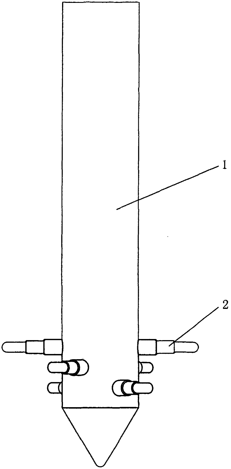
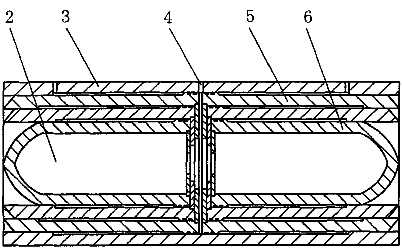
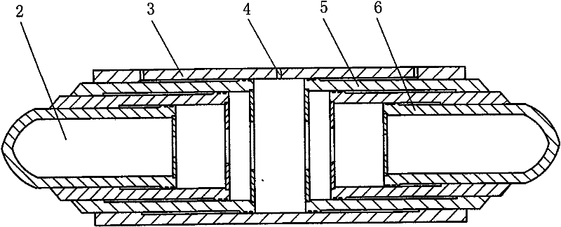
[0010] The foundation pile of the present invention is composed of a pile body 1 and a two-way multi-stage jack 2; the pile body 1 is cylindrical, and the lower part is a conical shape; the lower part of the pile body 1 is equipped with 2 to 4 two-way multi-stage jacks 2, which The installation angles are staggered. The two-way multi-stage jack 2 is composed of a shell 3 and two symmetrical movable oil cylinders 5 and 6; there is a hydraulic oil inlet 4 in the middle of the shell; the movable oil cylinders 5 and 6 are divided into three stages, set together, and installed symmetrically in the shell 3 within.
Login to View More PUM
 Abstract
The invention provides a foundation pile, relating to the foundation pile which is used under bridges and buildings. The foundation pile in the invention is composed of a pile body and a bidirectional multi-level jack, wherein, the pile body is in a cylinder shape and the lower part is in a conical shape; and the lower part of the pile body is provided with one to a plurality of bidirectional multi-level jack and the installation angles thereof are staggered mutually. When in use, the bidirectional multi-level jacks are recoiled inside the pile body; the pile body is driven underground through a pile driver, and then a hydraulic pump leads the bidirectional multi-level jack to push out of the pile body and stretch into a foundation layer laterally. By utilizing the bidirectional multi-level jack, the foundation pile expands the contact area between the foundation pile and the foundation, thus having stronger compressive resistance and pull-out resistance; in addition, the foundation pile has simple construction, reliable performance, no earth volume and no pollution, and can greatly reduce the number of piling and construction volume and reduce cost effectively.
Description
Technical field [0001] A foundation pile relates to foundation piles used under bridges and buildings. Background technique [0002] The foundation piles currently used under bridges or buildings are mostly cylindrical steel piles. The surface of the cylindrical steel pile is smooth, and the friction with the foundation is small, so its compressive and pull-out resistance are relatively small. In order to overcome this shortcoming, it is necessary to drive multiple piles to overcome it. This will increase the amount of construction and cost. Summary of the invention [0003] The purpose of the present invention is to provide a foundation pile with good compression and pullout resistance. [0004] The foundation pile of the present invention is composed of a pile body and a two-way multi-stage jack; the pile body is cylindrical, and the lower part is a conical shape; one to several two-way multi-stage jacks are installed in the lower part of the pile body, and their installation a...
Claims
Login to View More Application Information
Patent Timeline
 Patent Type & AuthorityPatents(China)
IPC IPC(8): E02D5/24E02D5/54E02D5/48
Inventor高荣江
Owner高荣江