Road wind generator

A generator and road wind technology, applied in the direction of wind power generation, wind engine, wind motor combination, etc., can solve the problems of wind energy not being fully utilized, energy loss, etc.

Inactive Publication Date: 2010-03-17
王川
View PDF0 Cites 11 Cited by
  • Summary
  • Abstract
  • Description
  • Claims
  • Application Information

AI Technical Summary

Problems solved by technology

However, trains, automobiles, subway locomotives, etc. in railways, expressways, subway tunnels and other places in my country and other countries are collectively referred to as land vehicles, and the wind energy generated during their travel has not been fully utilized. big loss

Method used


Image

  • Road wind generator
  • Road wind generator
  • Road wind generator

Examples


Embodiment Construction

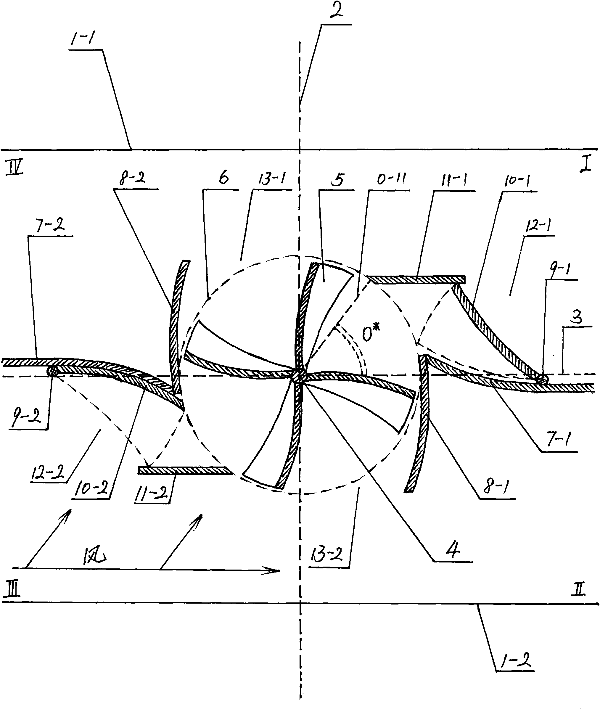
[0043] There are three main installation locations for road wind generators, namely: installed on one side of the road where land vehicles such as trains, automobiles, and subway locomotives pass by, installed on the side of the middle of the two opposite lanes, and installed on the top of the middle of the two opposite lanes ;When it is installed in various positions, the mechanical structure is adjusted and different. The road wind generator installed on the side of the middle of the two opposite lanes will be described in detail below:

[0044] Such as figure 1 : In railways, highways, expressways, and subway tunnels, between two parallel sides 1-1 and 1-2 adjacent to the inner sides of the two opposite lanes, a virtual common vertical line 2 is established; passing through 1-1, 1- The midpoint of 2 between 2 is parallel to 1-1 and 1-2, a virtual parallel line 3 is set, and the wind wheel shaft 4 perpendicular to the driving direction of 1-1 and 1-2 is set at the intersecti...


PUM


Abstract

The invention relates to a road wind generator, which belongs to the field of wind driven generators. The road wind generator has three mounting position modes on railways, express highways, subway tunnels and the like for land transport devices, and the three mounting position modes include the lateral surface on one side of a driveway, the lateral surface in the middle of opposite running driveways, and the top part in the middle of the opposite running driveways; a wind axle vertical to an opposite surface in a driving direction is arranged on the road wind generator and is connected with afan blade, and a one-way bearing is connected with a top cover and a bottom cover; a valve is connected with an air deflector through a door spindle, and the air deflector is connected with the top cover and the bottom cover; a gear is connected with the wind axle and is in meshed connection with a speed changer, and the speed changer is in meshed connection with a generator rotor shaft; and a supporting rod is connected with and fixes a machine body. The road wind generator uses the wind energy generated by the land transport devices of trains, automobiles, subway locomotives and the like inmoving, changes the wind energy into electric energy to change the waste into valuable, and can use natural wind energy to generate electricity so that the road wind generator accords with a nationalpolicy for environmental protection, energy-saving and emission reduction; besides, the road wind generators can be continuously arranged along the driveway direction to form generating sets for providing electric power for stations, towns and countries and parallel power supply on the way and providing electric power for electric locomotives and motor train units.

Description

Technical field: [0001] The utility model relates to a power generation device for converting wind energy generated during the running of a land vehicle and natural wind energy in a limited direction into electric energy, which belongs to the field of wind power generators. technical background: [0002] At present, in the field of wind power generators, natural wind power is mostly used to generate electricity. However, due to geographical and climatic conditions in my country, the wind force and wind speed in vast areas are weak, and the wind field conditions are relatively poor, which limits the establishment of natural wind power farms. Such as my country's vast central plains and other regions. However, trains, automobiles, subway locomotives, etc. in railways, expressways, subway tunnels and other places in my country and other countries are collectively referred to as land vehicles, and the wind energy generated during their travel has not been fully utilized. Big dra...

Claims


Application Information

Patent Timeline
Patent Type & Authority Applications(China)
IPC IPC(8): F03D9/00F03D3/00F03D3/04F03D9/25F03D9/46
CPCY02E10/72Y02E10/74Y02B10/30
Inventor 王川
Owner 王川
Why Eureka
Try Eureka