
Linearly-reciprocating piston compressor

A linear reciprocating, piston-type technology, used in piston pumps, liquid variable-capacity machinery, mechanical equipment, etc., can solve problems such as increased friction loss, sluggishness, and roller 6 impact noise.

Active Publication Date: 2010-03-17
ZHEJIANG HONGYOU AIR COMPRESSOR MFG
View PDF0 Cites 11 Cited by
  • Summary
  • Abstract
  • Description
  • Claims
  • Application Information

AI Technical Summary

Problems solved by technology

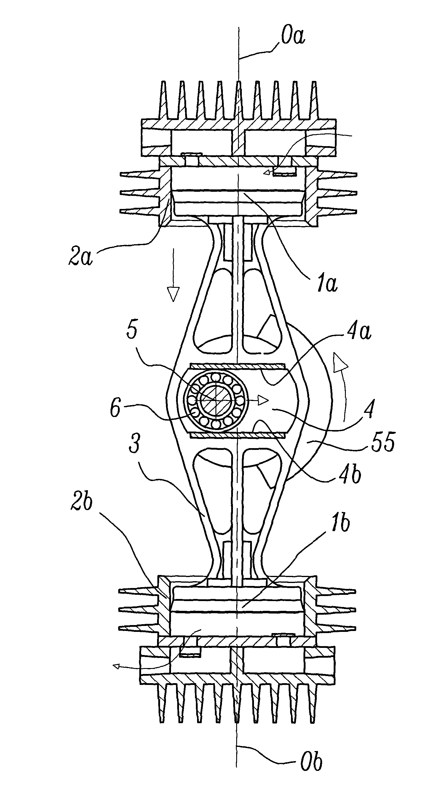
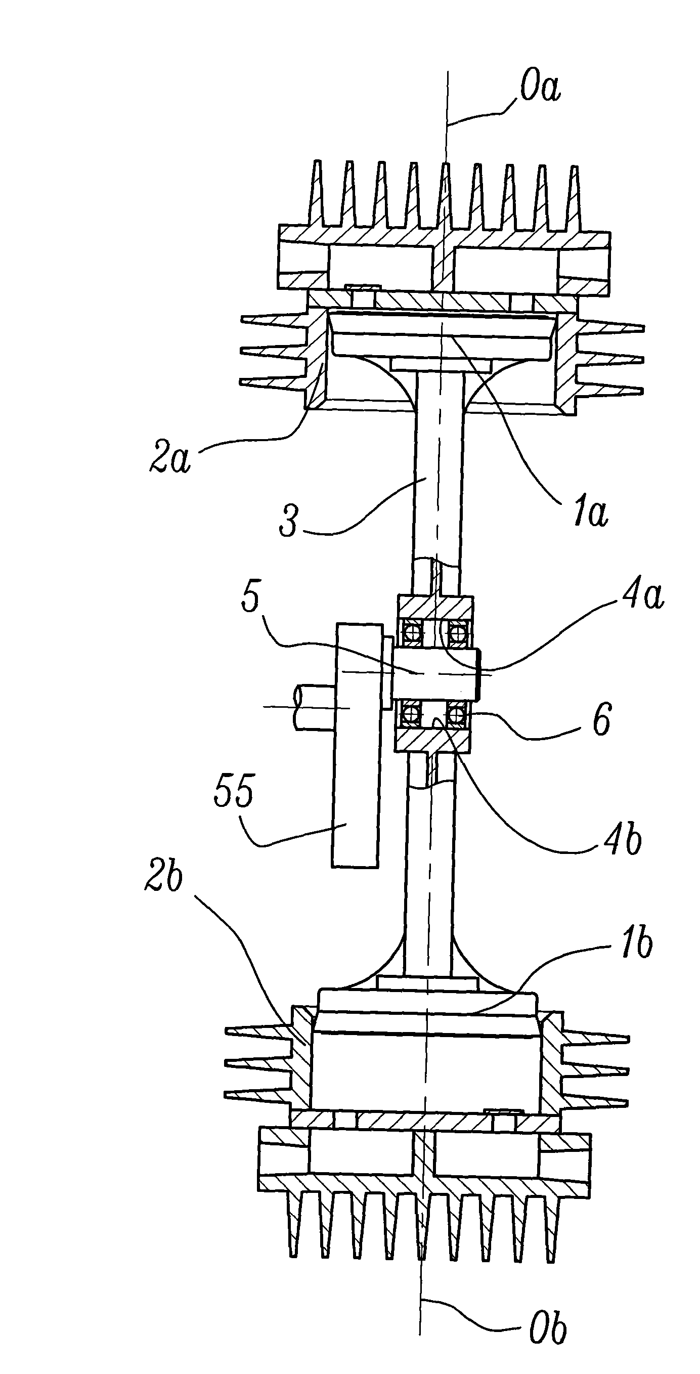
However, the above-mentioned compressor still needs to be improved, which is mainly manifested in the embarrassing situation where the fit gap between the guide rails 4a, 4b and the roller 6 is in a dilemma. If the fit gap is too small, the rollers 6 will easily contact at the same time. To the two guide rails 4a, 4b, the result is poor rolling and increased friction loss, and if the fit gap between the two is too large, it will inevitably cause the roller 6 to have a large impact on the guide rails 4a, 4b and generate noise.

Method used


Image

  • Linearly-reciprocating piston compressor
  • Linearly-reciprocating piston compressor
  • Linearly-reciprocating piston compressor

Examples


Embodiment Construction

[0022] The present invention will be further described below with specific embodiment, see Figure 3-8 :

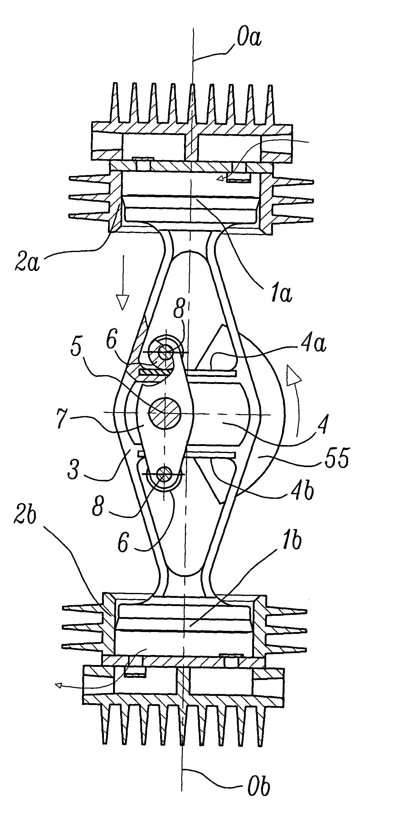
[0023] Figure 3 to Figure 8 A structural schematic diagram of a linear reciprocating piston compressor of the present invention is given, and the labels, names and functions of the parts in the figure are inherited figure 1 and figure 2 Shown is an existing linear reciprocating piston compressor. The linear reciprocating piston compressor of the present invention comprises: a motor, a crank driven by the motor and a crank pin 5 connected to the crank, two oppositely distributed pistons 1a, 1b and cylinders 2a, 2b, and a connecting rod 3, the The axes 0a, 0b of the cylinders 2a, 2b are arranged parallel to each other or coaxially (there is a certain manufacturing error and assembly error allowed), and the pistons 1a, 1b are arranged in the cylinders 2a, 2b and slidably fit with them. The two ends of the rod 3 are respectively connected with the two pistons 1a, 1b, an...


PUM


Abstract

The invention relates to a linearly-reciprocating piston compressor, belonging to the filed of the compressor. The linearly-reciprocating piston compressor comprises a crank pin, a connecting rod, twopistons and two air cylinders; the two pistons and the two air cylinders are distributed oppositely; the two pistons are arranged in the air cylinders and are matched with the air cylinders in a sliding way; two ends of the connecting rod are respectively connected with the two pistons; the middle part of the connecting rod is provided with two parallel guide rails and an auxiliary connecting rod; the ends of the auxiliary connecting rod are provided with shaft pins; rollers are rotationally sleeved on the shaft pins; and the rollers are matched with the guide rails in a rolling contact way.One of the two guide rails is used for driving one piston to carry out compression stroke, the other guide rail is used for driving the other piston to carry out air inlet stroke, and the two guide rails work alternatively, thus the match clearance between the rollers and the guide rails can be effectively reduced or fully eliminated, the rollers are kept contacting the guide rails in a rolling way, the friction between the rollers and the guide rails is mitigated, and the noise from the impact of the rollers and the guide rails is reduced. The linearly-reciprocating piston compressor can be used for producing the compressor, the vacuum pump, the hydraulic pump and the water pump.

Description

technical field [0001] The invention belongs to the technical field of mechanical engineering, in particular to a linear reciprocating piston compressor. Background technique [0002] As we all know, the current compressor mainly uses a crank-connecting rod reciprocating mechanism, which is mainly composed of a motor, a crank, a connecting rod and a piston. In this way, the conversion between the rotary motion of the crank and the reciprocating motion of the piston is realized. Obviously, the connecting rod of the traditional crank-and-link mechanism works in an oscillating motion, so the force exerted by the connecting rod on the piston is an oscillating force, which will not only cause the piston to slap the cylinder and generate noise, but also cause noise. Cause the piston to act on the cylinder with greater side pressure and increase friction loss. In order to overcome the above disadvantages of the traditional crank-connecting rod mechanism, a linear reciprocating pi...

Claims


Application Information

Patent Timeline
IPC IPC(8): F04B35/01F04B39/00
Inventor 陈君立耿爱农孙世杰阮勤江
Owner ZHEJIANG HONGYOU AIR COMPRESSOR MFG
Learn More