
Motion distorting compensation method of mechanical scanning type imaging sonar

A technology of mechanical scanning and distortion compensation, which is applied in the directions of re-radiation of sound waves, utilization of re-radiation, and measuring devices, etc., which can solve problems such as large accumulation of robot positioning errors, rare images, and weakened AUV navigation and positioning capabilities.

Inactive Publication Date: 2011-11-09
OCEAN UNIV OF CHINA
View PDF0 Cites 0 Cited by
  • Summary
  • Abstract
  • Description
  • Claims
  • Application Information

AI Technical Summary

Problems solved by technology

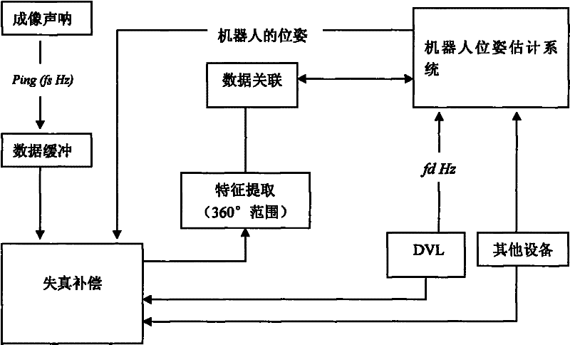
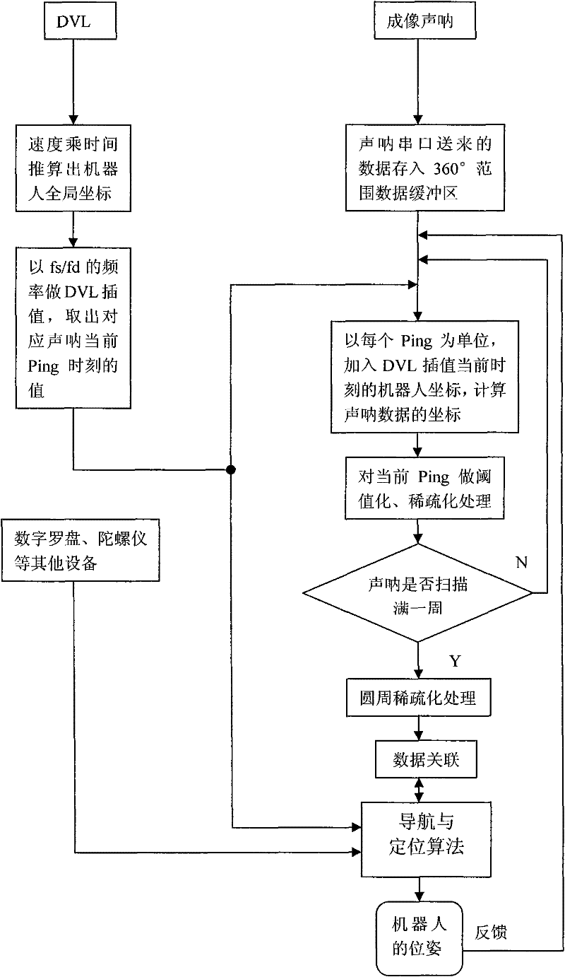
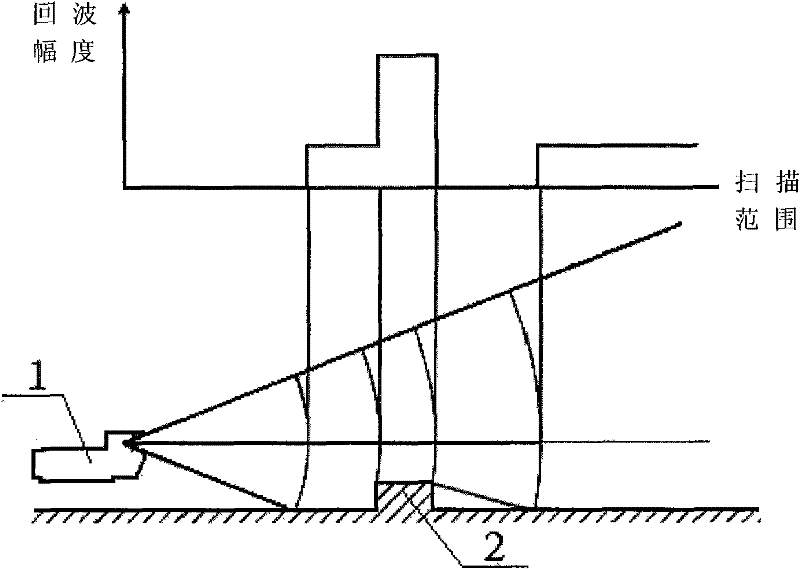
However, due to the uncertainty of the sonar angle, the distance information it provides is more difficult to interpret than the information provided by laser scanning and other equipment; moreover, the autonomous navigation and positioning method needs the environmental characteristics around the robot as input, and updates the position of the robot after processing. Generally, the point features obtained by the sonar scan for a week are regarded as a processing cycle. The sonar emits a sound wave to obtain an echo data. When the sound wave encounters an obstacle, it is reflected in the echo data as a high amplitude value. After the point feature extraction algorithm After extracting the required point feature positions, a feature map of the robot’s surrounding environment can be obtained after a week of sonar scanning. If the robot’s position is still, a 2D image of its surrounding environment can be drawn according to the above ideas, but in fact the robot is It is always moving, and the slow scanning of mechanical scanning imaging sonar takes a certain amount of time. The position of the robot is not fixed at the same position, and then the sonar image drawn by the same method will be distorted. The sonar image is used by the navigation method, which will cause the robot's positioning error to accumulate more and more, thus weakening the ability of AUV navigation and positioning
Currently, there are very few methods on how to compensate for the image distortion caused by the motion of the mechanical scanning sonar

Method used


Image

  • Motion distorting compensation method of mechanical scanning type imaging sonar
  • Motion distorting compensation method of mechanical scanning type imaging sonar
  • Motion distorting compensation method of mechanical scanning type imaging sonar

Examples


Embodiment Construction

[0022] In the present invention, the autonomous navigation method described above takes SLAM as an example, and its execution process can be roughly divided into three stages: prediction, observation and update. First, the robot pose and point features are stored in an independent state vector, and then the system state is estimated through an iterative recursive process of first prediction and then observation, so as to realize the positioning of the robot and the creation of a feature map. In the prediction stage, the dead reckoning method in the usual sense is actually implemented, which causes a large error in the state estimation of the robot; the feature value is obtained in the observation stage, and if the feature is observed for the first time, it is added to the state vector; if the feature already stored in the state vector, update the values ​​of features already in the AUV and map. The motion distortion compensation method that the present invention adopts is afte...


PUM


Abstract

The invention belongs to an image data processing method, in particular to a motion distorting compensation method of a mechanical scanning type imaging sonar. The invention aims at providing distortionless real-time environmental objective characteristics for underwater robots used for realizing autonomous navigation and positioning. The method comprises the following steps: acquiring data by the imaging sonar, calculating the coordinates and the interpolation of the robots, carrying out the distorting compensation and point characteristic extraction, processing and feeding back a robot posture estimation system; and the method is applied to the underwater robots which take autonomous navigation and positioning as the objective and ensures that the robots can accurately perceive the position in the environment, thereby completing the control on the self motion posture to realize the expected movement locus.

Description

technical field [0001] The invention belongs to an image data processing method, in particular to a motion distortion compensation method of a mechanical scanning imaging sonar. Background technique [0002] Autonomous Underwater Vehicles (AUV for short) to achieve true autonomous navigation, a large part depends on their ability to establish accurate maps and their own positioning according to the route they have passed. This is the focus of the AUV research field in recent years. Based on this, many excellent navigation and positioning methods have been proposed, such as the well-known "simultaneous positioning and map construction method" referred to as the SLAM method. Simply put, the success of navigation generally includes the following four parts: perception, the robot must be able to interpret its sensor information and extract meaningful data; localization, the robot must determine its position in the environment; cognition, the robot must decide how to Action to a...

Claims


Application Information

Patent Timeline
Patent Type & Authority Patents(China)
IPC IPC(8): G01S7/52G01S7/539G01S15/89
Inventor 何波赵帅田舒陈树娟宋沛
Owner OCEAN UNIV OF CHINA
Learn More