
Counterflow focusing method and device implementing method

A focusing and focusing ring technology, which is applied in the direction of installation, color TV parts, TV system parts, etc., can solve the problems of inability to adapt to special CCM requirements, single-thread focusing speed limitation, and inability to achieve focusing accuracy, etc. problem, to achieve the effect of simple structure, convenient focusing and fast speed

Active Publication Date: 2010-03-17
安徽光阵光电科技有限公司
View PDF0 Cites 4 Cited by
  • Summary
  • Abstract
  • Description
  • Claims
  • Application Information

AI Technical Summary

Problems solved by technology

This kind of focusing device has a simple structure, but because the lens needs to rotate, it is not suitable for non-rotationally symmetrical lenses. In addition, the focusing accuracy is easily affected by the minimum pitch of stable processing, so it cannot achieve high focusing accuracy; at the same time, when the focusing stroke When it is too long, the focusing speed of single thread is greatly limited
Therefore, conventional focusing devices cannot meet the needs of special CCMs

Method used


Image

  • Counterflow focusing method and device implementing method
  • Counterflow focusing method and device implementing method
  • Counterflow focusing method and device implementing method

Examples


Embodiment

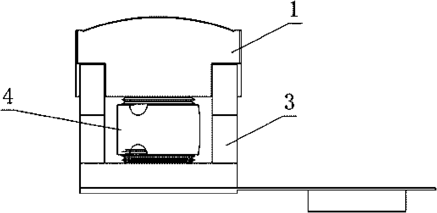
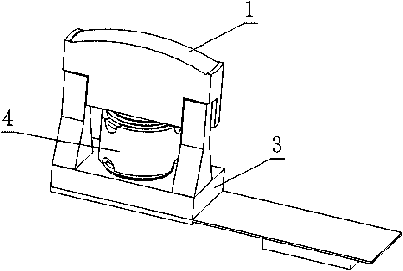
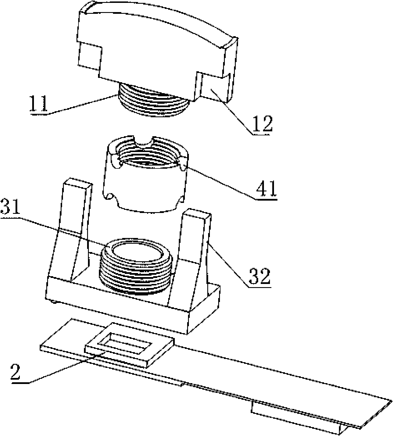
[0021] Example: see figure 1 , figure 2 with image 3 , a progressive focusing method provided by an embodiment of the present invention, which includes the following steps:

[0022] (1) A lens 1 is set to focus on the scene. A lower screwing part 11 with an external thread is provided at the center of the bottom of the lens 1, and a lens that can guide it along the optical axis is provided on both sides of the lower part of the lens 1. The chute 12 that slides up and down;

[0023] (2) An image sensor 2 and a mirror base 3 with a cavity in the lower part are arranged in the focus range of the lens 1 along the optical axis direction, the image sensor 2 is inserted into the cavity, and placed on the mirror base 3 It is provided with a through hole that allows the lens 1 to focus the scene onto the image sensor 2. The edge of the through hole protrudes upwards to form an upper screwed part 31 with external threads. On the upper screwed part 31 The external thread on the low...


PUM


Abstract

The invention discloses a counterflow focusing method, comprising the following steps: 1) arranging a lens; 2) arranging an image sensor and a lens seat with a hollow cavity at the lower part are arranged in a focusing range of the lens; 3) arranging a focusing ring for adjusting the distance of the lens and the lens seat, respectively arranging internal threads matched with external threads of anupper screwing part and a lower screwing part on the upper part and the lower part of the focusing ring, rotating the focusing ring, and forcing the lens and the lens seat to close or separate towardthe center of the focusing ring simultaneously by the internal thread thereof, thus realizing the purpose of focusing by adjusting the distance of the lens and the image sensor. The method can focuswith fastness and high efficiency, and can adopt irrotational and symmetrical lens as the lens does not need to rotate; and the device has simple structure, adopts a counterflow focusing mode, has convenient and fast focusing and high focusing precision, improves product performance and is beneficial to the development of enterprises.

Description

technical field [0001] The invention relates to an adjustment device in a photographing device, in particular to a progressive focusing method and a device for implementing the method. Background technique [0002] CMOS Camera Module (CMOS Camera Module) is referred to as CCM, which is the core device for various new-generation portable camera equipment. Compared with traditional camera systems, it has the advantages of miniaturization, low power consumption, low cost, and high image quality. It can be widely used in camera phones, videophones, car assisted driving, security monitoring and other fields. The CCM is mainly composed of SENSOR, LENS, FPC / PCB, CONNECTOR and other parts. Focusing is the most important link in CCM production, and accurate and fast focusing is one of the key production technologies of CCM. The existing CCM focusing structure is to connect the lens and the lens holder with a thread, and the thread is screwed in or out by rotating the lens, and then...

Claims


Application Information

Patent Timeline
Patent Type & Authority Applications(China)
IPC IPC(8): G02B7/04H04N5/225
Inventor 沈振权舒伟平曹后平田野
Owner 安徽光阵光电科技有限公司
Learn More