
Detachable fixing component

A fixed component and detachable technology, which is applied in the field of detachable fixed components, can solve the problems that the fixture can only be scrapped, the fixture is deformed, and cannot be recycled, and achieves the effect of reducing manufacturing costs and being easy to disassemble and assemble.

Inactive Publication Date: 2010-03-17
CORETRONIC (SUZHOU) CO LTD
View PDF0 Cites 36 Cited by
  • Summary
  • Abstract
  • Description
  • Claims
  • Application Information

AI Technical Summary

Problems solved by technology

When the optical film is temporarily fixed by clamping, the clamp must be removed before starting the LCD panel assembly operation, thus causing deformation of the clamp
Therefore, the existing clamps can only be scrapped after being disassembled and cannot be recycled, which leads to an increase in manufacturing costs
In addition, when the optical film is temporarily fixed by adhesive tape, after the reliability test, the glue on the optical film is also likely to have residual glue

Method used


Image

  • Detachable fixing component
  • Detachable fixing component
  • Detachable fixing component

Examples


Embodiment Construction

[0030] The following descriptions of the various embodiments refer to the accompanying drawings to illustrate specific embodiments in which the present invention may be practiced. The directional terms mentioned in the present invention, such as "upper", "lower", "front", "rear", "left", "right", etc., are only referring to the directions of the attached drawings. Accordingly, the directional terms are used to illustrate, not to limit, the invention.

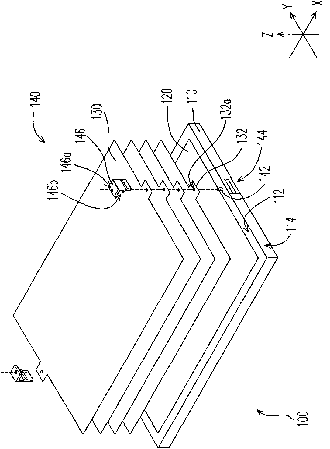
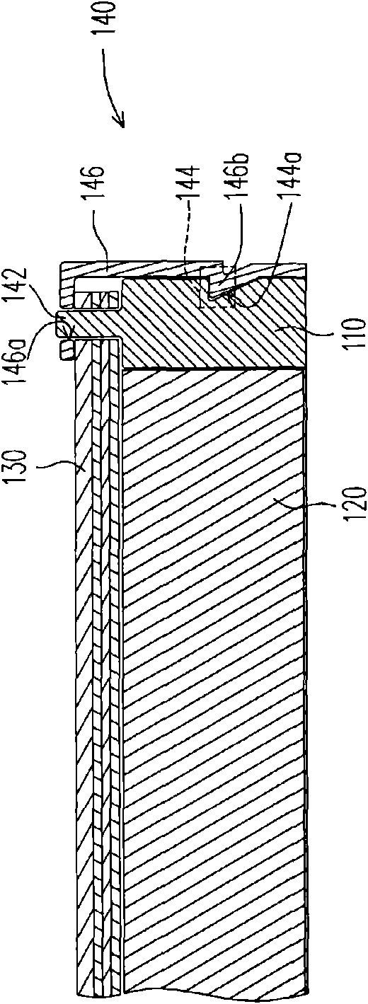
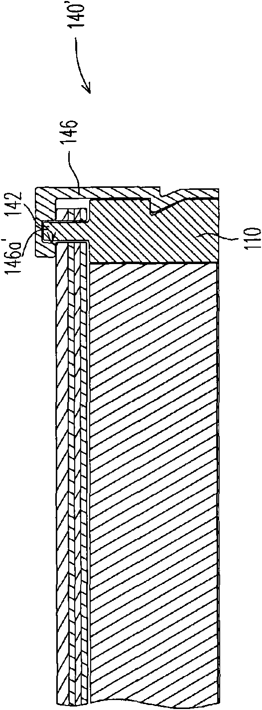
[0031] figure 1 It is an exploded view of a backlight module according to an embodiment of the present invention. Please refer to figure 1 , the backlight module 100 is suitable for use as a surface light source of a liquid crystal display. The backlight module 100 includes a plastic frame 110 , an illuminating device 120 , a plurality of optical films 130 and a plurality of detachable fixing components 140 . The lighting device 120 is mounted on the plastic frame 110 . In this embodiment, the illuminating device 120 has a ...


PUM


Abstract

The invention discloses a detachable fixing component, which is suitable for fixing one side of at least one optical membrane of a backlight module on one side of a rubber frame of the backlight module. The fixing component comprises at least one positioning convex column, a limit part and a fixed stop block. The positioning convex column is suitable for being fixedly arranged at the upper lateralsurface of the rubber frame. The limit part is suitable for being arranged on the outer lateral surface of the rubber frame and is provided with a limit groove, wherein the outer lateral surface is connected with the upper lateral surface. The fixed stop block is provided with a positioning hole sleeved with the positioning convex column and a blocking hook blocked with the limit groove. The positioning hole of the fixed stop block is sleeved with the positioning convex column and the blocking hook is blocked with the limit groove so that the optical membrane is clamped by the fixed stop block and the rubber frame, at the moment, the positioning convex column is matched with the limit part to make the fixed stop block have translation freedom degree relative to the positioning convex column, while the blocking hook and the limit groove limit the translation freedom degree.

Description

【Technical field】 [0001] The present invention relates to a detachable fixing assembly, and in particular to a detachable fixing assembly of an optical film of a backlight module. 【Background technique】 [0002] A liquid crystal display module (LCM) is mainly composed of a liquid crystal panel (liquid crystal panel) and a backlight module, wherein the function of the backlight module is to provide a side light source required by the liquid crystal panel to display images. The backlight module includes components such as a light guide plate, a reflector, a light source, a multilayer optical film, and a plastic frame. These optical films are, for example, diffusers, prisms, polarizers, and concentrators, etc., and are disposed on the upper surface of the light guide plate to process light from the light guide plate. The liquid crystal panel and the backlight module are manufactured individually and then assembled into a liquid crystal panel module. Therefore, before assembli...

Claims


Application Information

Patent Timeline
IPC IPC(8): G02F1/13G02F1/13357
Inventor 胡发学
Owner CORETRONIC (SUZHOU) CO LTD
Learn More