
Range switch

A technology of a band switch and a main body, applied in the field of band switches, can solve the problems of increasing production costs, increasing the assembly steps of the production line, unable to adjust the torque, etc., and achieving the effect of reducing dirt

Inactive Publication Date: 2010-03-17
LNC TECH CO LTD
View PDF0 Cites 9 Cited by
  • Summary
  • Abstract
  • Description
  • Claims
  • Application Information

AI Technical Summary

Problems solved by technology

[0002] The conductive principle of the band switch is to directly drive the contact piece to connect the charged end to the non-charged end. However, during the internal use of these switches, there will be dust, moisture, and powder generated by friction between the contact piece and the contact point (resistance substrate). The dirt generated by the action of these substances will increase the unnecessary electrical impedance in the circuit, and in severe cases, the circuit will fail or even be interrupted. Moreover, the existing switch is extremely inconvenient to assemble due to the large number of parts, which increases the assembly steps of the production line and improves the efficiency of the circuit. Production cost; moreover, the existing band switch cannot adjust the torque mechanism, so it can be seen that the above-mentioned conventional items still have many deficiencies, which is not a good design and needs to be improved urgently

Method used


Image

  • Range switch
  • Range switch
  • Range switch

Examples


no. 2 example

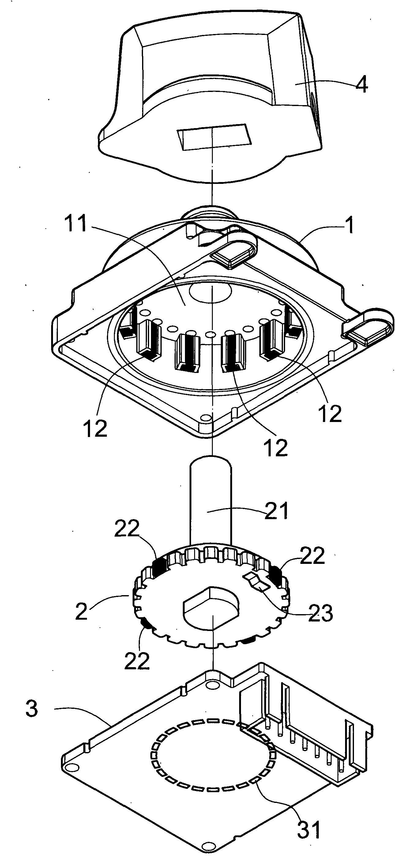
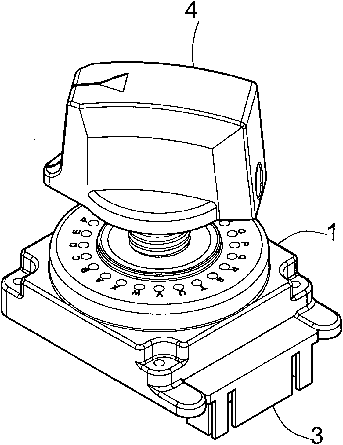
[0022] The main body 1 has an accommodating area 11;

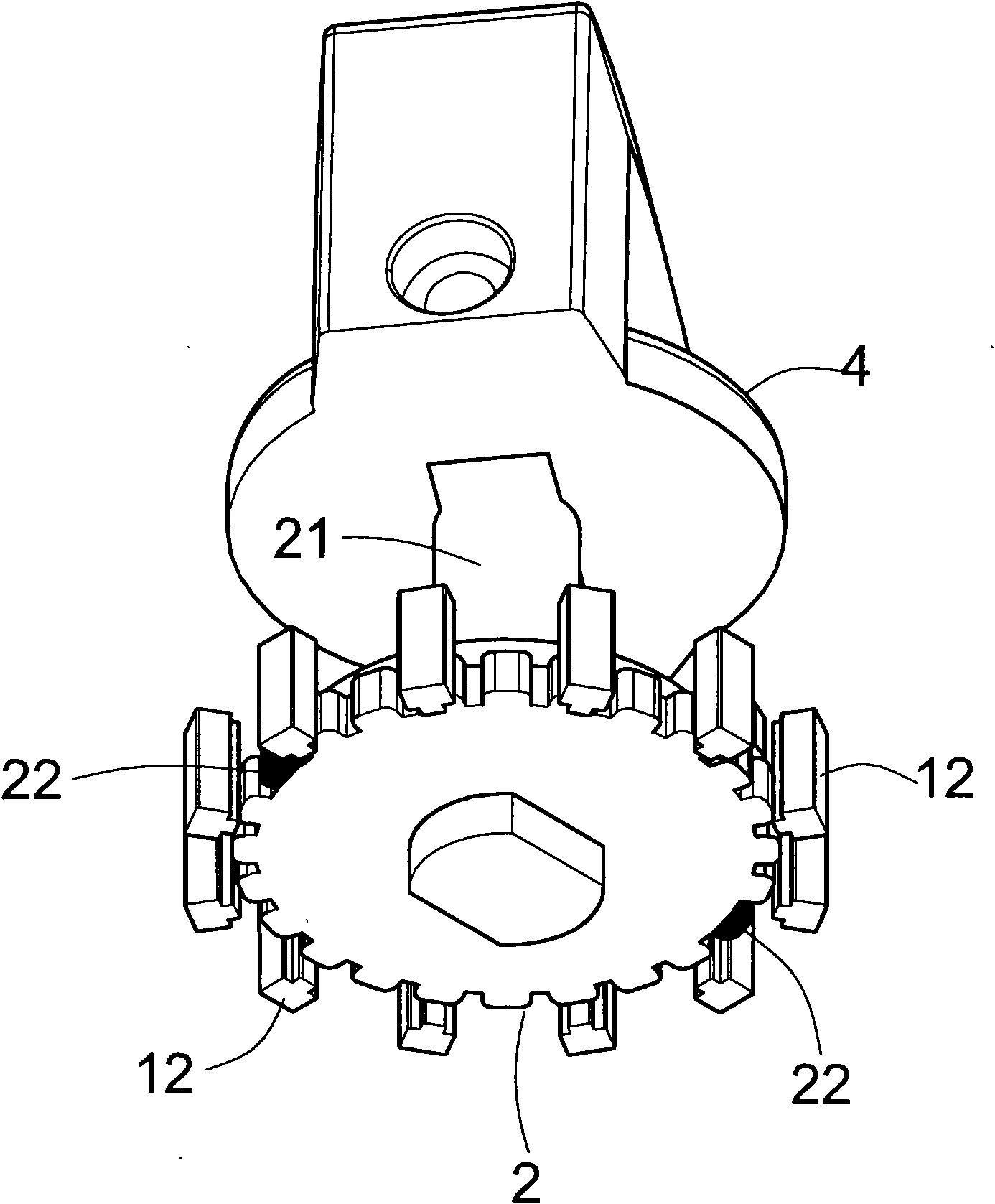
[0023] The rotating part 2 is assembled in the accommodation area 11 of the main body 1. The rotating part 2 is arranged on the main body 1 with a through shaft 21. The bottom surface of the rotating part 2 is equipped with at least one magnetic body 22 (or metal body) and at least one contact piece. twenty three;

[0024] The bottom cover 3 is used to cover the accommodating area 11 of the main body 1, and the magnetic bodies 32 are arranged at equal distances in a ring shape, and at least one electronic component 31 can be directly or indirectly contacted with the contact piece 23 of the rotating part 2, and the bottom cover 3 The electronic component 31 is provided with resistance elements with different coefficients; the magnetic body 32 is a magnet, a permanent magnet, an electromagnet or an electromagnetic coil, and the electromagnetic coil can input electric energy to generate a magnetic field.

[0025] In the band...


PUM


Abstract

The invention provides a range switch composed of a main body, a rotating part and a bottom cover. The main body is provided with a holding area, and magnetic substances are arranged around the innercircumference of the main body; the rotating part is arranged on the main body by a transmission axis, and the side edge of the rotating part is provided with at least one magnetic substance, and thebottom surface is fixedly provided with contact chips; the bottom cover is used for covering the holding area of the main body and comprises at least one electronic component which can contact the contact chips of the rotating part; moreover, the electronic component is provided with resistor elements with different coefficients. After the rotating part is rotated, the rotating part and the magnetic substances arranged around the main body can attract mutually, thereby achieving the goal of providing no-contact fine-tuning output.

Description

technical field [0001] The invention relates to a band switch, in particular to a band switch in which a switch knob uses magnetic attraction for positioning and movement to perform work to achieve functions such as amplification, adjustment, and conversion. Background technique [0002] The conductive principle of the band switch is to directly drive the contact piece to connect the charged end to the non-charged end. However, during the internal use of these switches, there will be dust, moisture, and powder generated by friction between the contact piece and the contact point (resistance substrate). The dirt generated by the action of these substances will increase the unnecessary electrical impedance in the circuit, and in severe cases, the circuit will fail or even be interrupted. Moreover, the existing switch is extremely inconvenient to assemble due to the large number of parts, which increases the assembly steps of the production line and improves the efficiency of th...

Claims


Application Information

Patent Timeline
IPC IPC(8): H01H19/02H01H19/03H01H1/54H01H19/54H01C10/16H01C10/50
Inventor 李武嶰
Owner LNC TECH CO LTD
Learn More