Elevator

A technology of elevators and control devices, which is applied to elevators, transportation and packaging, elevators, etc. in buildings, and can solve problems such as driving force limitations

Active Publication Date: 2010-03-17
MITSUBISHI ELECTRIC CORP
View PDF1 Cites 11 Cited by
  • Summary
  • Abstract
  • Description
  • Claims
  • Application Information

AI Technical Summary

Problems solved by technology

[0004] In the above-mentioned conventional elevator apparatus, when the drive unit fails, only the normal drive unit is driven irrespective of the location of the failure. Therefore, only the encoder in the drive unit fails, and the equipment other than the encoder is normal. In this case, the driving unit cannot be used, and the driving force is quite limited

Method used


Image

  • Elevator
  • Elevator
  • Elevator

Examples


Embodiment approach 1

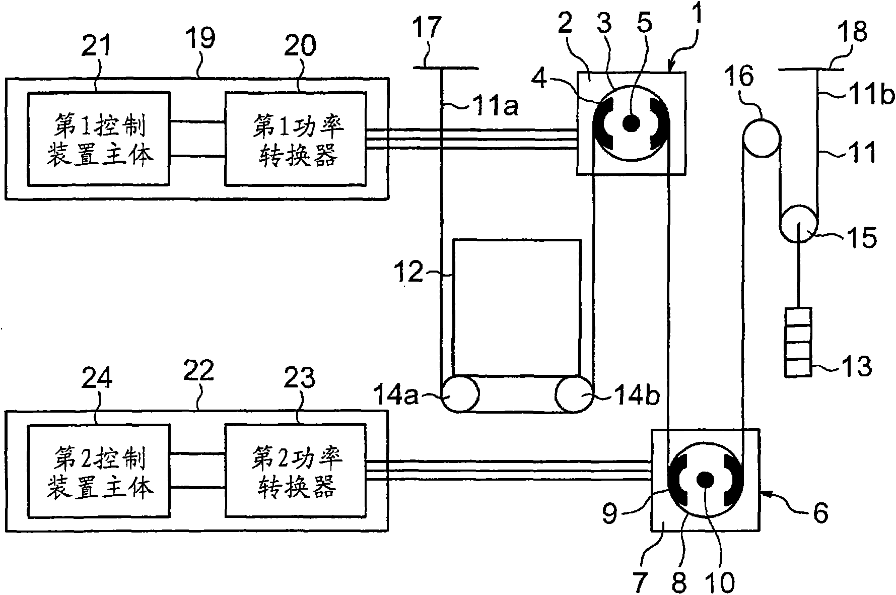
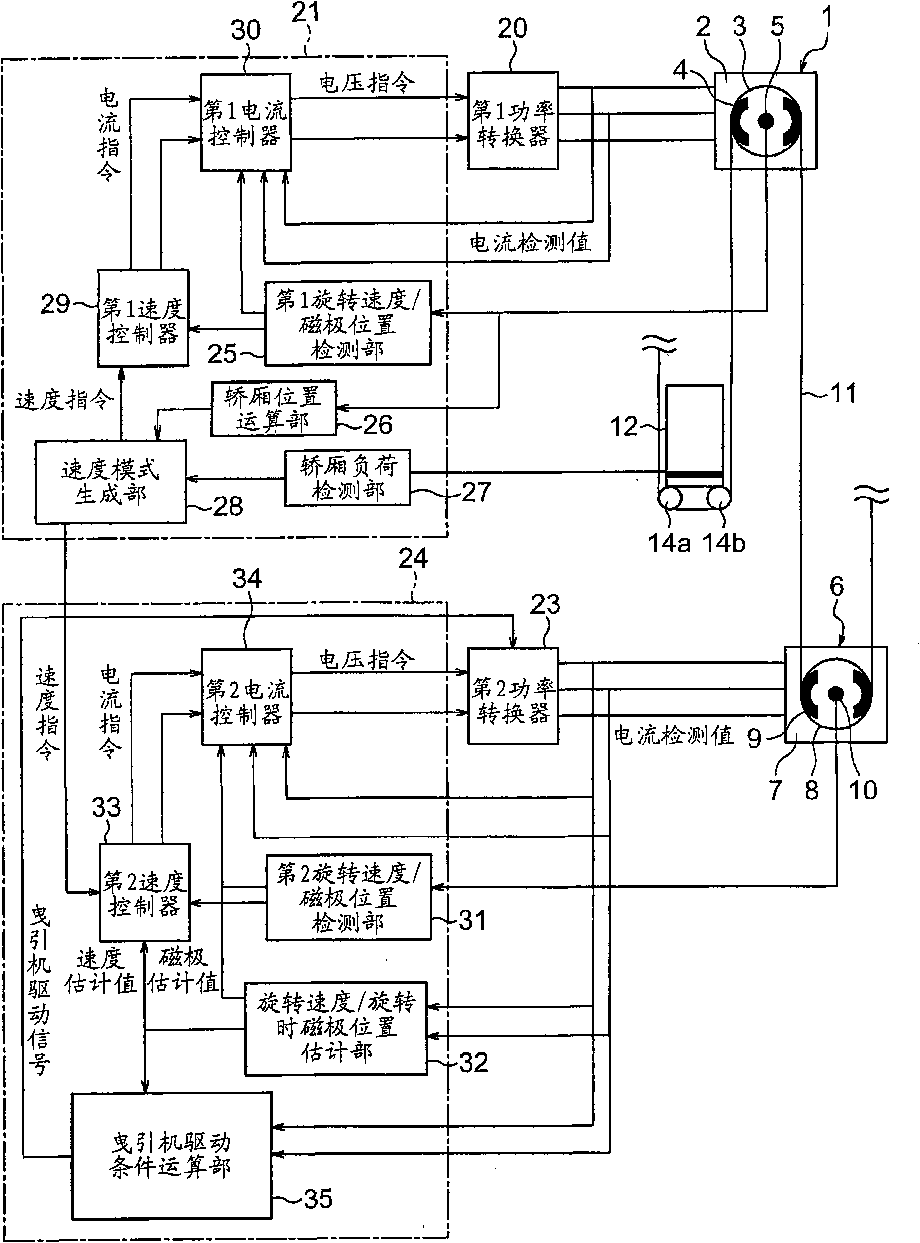
[0014] figure 1 It is a block diagram showing the elevator apparatus according to Embodiment 1 of the present invention. In the figure, the first hoisting machine 1 is provided on the upper part of the hoistway. The first traction machine 1 has a first motor 2, a first drive sheave 3 rotated by the first motor 2, a first brake 4 for braking the rotation of the first drive sheave 3, and a The first encoder 5 that generates a signal corresponding to the rotation of the sheave 3 is driven. The first drive sheave 3 and the first motor 2 are arranged coaxially.

[0015] The second traction machine 6 is provided at the lower part of the hoistway. The second traction machine 6 has a second motor 7, a second driving sheave 8 rotated by the second motor 7, a second brake 9 for braking the rotation of the second driving sheave 8, and a The second encoder 10 that generates a signal corresponding to the rotation of the sheave 8 is driven. The 2nd drive sheave 8 and the 2nd electric m...

Embodiment approach 2

[0051] under, Figure 5 It is a configuration diagram showing an elevator apparatus according to Embodiment 2 of the present invention. In Embodiment 1, the elevator apparatus of the 2:1 rope system was shown, and in Embodiment 2, the elevator apparatus of the 1:1 rope system is demonstrated.

[0052] In the drawing, first and second hoisting machines 1 and 6 are provided on the upper part of the hoistway. A plurality of (only one is shown in the figure) first main ropes 41 serving as suspension means are wound around the first drive sheave 3 . A plurality of (only one is shown in the figure) second main ropes 42 serving as suspension means are wound around the second drive sheave 8 . The car 12 is connected to one end of the first main rope 41 and one end of the second main rope 42 . That is, the car 12 is suspended by the first and second main ropes 41 and 42 .

[0053] A first counterweight 43 is connected to the other end of the first main rope 41 . The second counter...


PUM


Abstract

A controller for controlling a plurality of hoists in an elevator has a rotation-speed and magnetic-pole-position-in-rotation estimating part for estimating the rotation speed and the magnetic pole position in rotation of each motor. If a cage is driven while one of encoders fails, only the motor of the hoist equipped with a normal encoder is driven in a low speed region at a predetermined or lower rotation speed. The motor of the hoist equipped with the normal encoder is driven and also the motor of the hoist equipped with a failing encoder is driven based on an estimation value by the rotation-speed and magnetic-pole-position-in-rotation estimating part out of the low speed region faster than the predetermined rotation speed.

Description

technical field [0001] The invention relates to an elevator installation having a plurality of traction machines for raising and lowering a car. Background technique [0002] In conventional elevator devices, when a failure of any one of a plurality of driving units is detected, the driving force that can be generated by the general command unit for the normal driving unit and the necessary driving force required to raise and lower the car Calculate the difference, and only output the operation command to the normal drive unit. Accordingly, low-speed operation or normal operation is performed within the range of the driving force that can be generated (for example, refer to Patent Document 1). [0003] Patent Document 1: Japanese Patent Laid-Open No. 2006-199395 [0004] In the above-mentioned conventional elevator apparatus, when the drive unit fails, only the normal drive unit is driven irrespective of the location of the failure. Therefore, only the encoder in the drive...

Claims


Application Information

Patent Timeline
Patent Type & Authority Applications(China)
IPC IPC(8): B66B5/02
CPCB66B9/00B66B1/285B66B5/02B66B1/28
Inventor 马场俊行
Owner MITSUBISHI ELECTRIC CORP
Why Eureka
Try Eureka