Dust collector dust-full indicator

A technology of indicators and vacuum cleaners, applied in the direction of suction filters, etc., can solve the problems of difficult control of elasticity, complicated installation, lateral offset, etc., and achieve the effects of easy production and installation, improved production efficiency, and simple structure

Inactive Publication Date: 2010-03-24
LG ELECTRONICS (TIANJIN) APPLIANCES CO LTD
View PDF0 Cites 3 Cited by
  • Summary
  • Abstract
  • Description
  • Claims
  • Application Information

AI Technical Summary

Problems solved by technology

[0008] However, sometimes the elasticity of the elastic body 7s (such as a spring) of the dust-full indicator of the vacuum cleaner is not easy to control, and it is prone to lateral deviation, which causes the spring to be easily stuck and does not move, so that the indicator device 7d has poor dust-full display and cannot Move to the observation window in time, so that the indicator ca

Method used


Image

  • Dust collector dust-full indicator
  • Dust collector dust-full indicator
  • Dust collector dust-full indicator

Examples


Example Embodiment

[0021] In order to enable those skilled in the art to better understand the solution of the present invention, the present invention will be further described in detail below with reference to the accompanying drawings and embodiments.

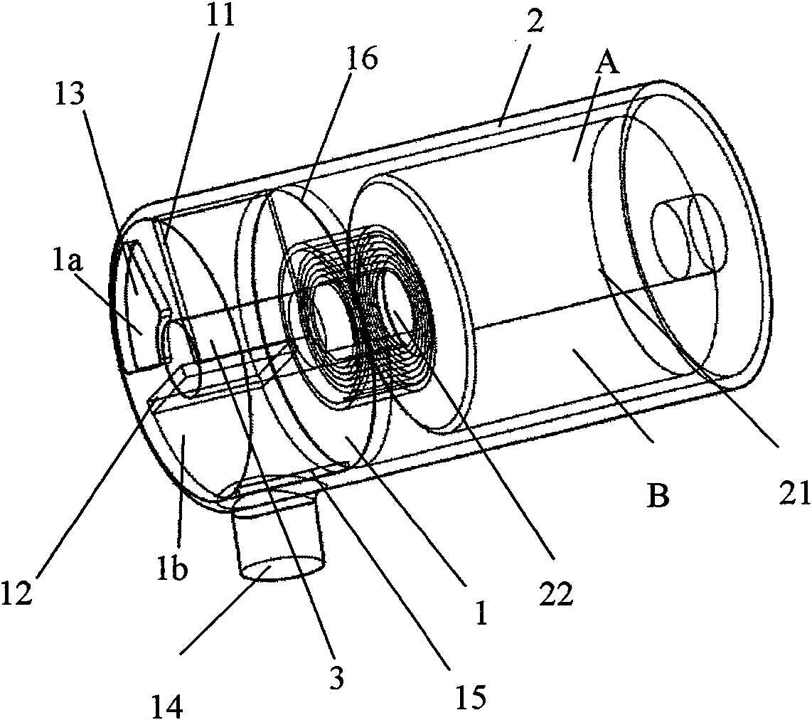
[0022] Such as image 3 , Figure 4 , Figure 5 As shown, the present invention provides a dust-full indicator for a vacuum cleaner. The indicator is a rotating indicator. The indicator includes a front chamber 1 and a rear chamber 2. The two chambers are respectively located in the indicator. The left and right ends of the indicator pass image 3 , Figure 5 The cavity partition plate 16 shown is divided into two chambers, a front chamber 1 and a rear chamber 2. The front chamber 1 and the rear chamber 2 are not connected, and the front chamber 1 and the rear chamber 2 are connected by a rotating shaft 3. connection.

[0023] The rear cavity 2 is a chamber for installing action elements. A cylindrical barrel 21 and a coil spring 22 are provided ...


PUM


Abstract

The invention discloses a dust collector dust-full indicator comprising a front cavity and a rear cavity, wherein the front cavity and the rear cavity are respectively arranged on two ends of the indicator and are connected via a rotation axis; the rear cavity is provided with a cylinder and a coil spring, wherein the cylinder and the coil spring are fixed on the rotation axis in the rear cavity;the upper cylinder surface and the lower cylinder surface of the cylinder are provided with two different colors; a rib plate and a rotation plate are arranged in the front cavity and divide the firstcavity into a first space and a second space; the rip plate is fixedly arranged on the inner side surface of the front cavity of the indicator; the rotation plate is fixedly arranged on the rotationaxis in the front cavity; the first space is communicated with the outside of the dust collector via an air inlet; and the second space is communicated with the dust collecting chamber in the dust collector via an air outlet. The invention effectively avoids the problem of spring lateral excursion, ensures that users can accurately know the amount change situation of foreign matters, such as dustcollected by the dust collector and the like, and has simple structure and convenient installation.

Description

technical field [0001] The invention relates to the technical field of mechanical dust removal, in particular to a dust full indicator of a vacuum cleaner. Background technique [0002] Such as figure 1 As shown, a general vacuum cleaner 10 body includes a motor drive chamber 4 and a dust collection space 2 . The motor housing H with a fan (not shown) and a motor (not shown) that generates suction is installed in the above-mentioned motor drive chamber 4 . An exhaust member 9 is provided at the rear of the motor housing H to exhaust the air separated from the foreign matter to the outside of the vacuum cleaner 10 body. [0003] A suction inlet 1 is formed on the front side of the dust collection space 2 in front of the above-mentioned motor drive chamber 4, and a motor and a fan that can generate suction are provided between the dust collection space 2 and the exhaust member 9, so that the suction inlet 1 and The suction hose 6 connected to the suction inlet forms a sucti...

Claims


Application Information

Patent Timeline
IPC IPC(8): A47L9/19
Inventor 肖宗亮
Owner LG ELECTRONICS (TIANJIN) APPLIANCES CO LTD
Why Eureka
Try Eureka