Imaging component for projection system

A technology of imaging components and projection systems, applied in optical components, installation, optics, etc., can solve problems such as damage to the projection system, inconvenient use, and arrangements that affect the heat dissipation of the projection system

Inactive Publication Date: 2010-03-24
DELTA ELECTRONICS INC
View PDF0 Cites 42 Cited by
  • Summary
  • Abstract
  • Description
  • Claims
  • Application Information

AI Technical Summary

Problems solved by technology

But when wanting to project the image pattern of the original display ratio, the user needs to put the projection system back to the horizontal position, which increases the inconvenience of use, and the placement area of ​​this arrangement is small, and the projection system is relatively large. unstable
[0006] On the other hand, changing the placement of the projection system is not only inconvenient to use and causes the projection system to be placed more unstable, but also the lamp inside the projection system has a specific angle of use. Improper rotation of the projection system may cause damage to the wick and shorten the life of the lamp. , but also affect the arrangement of projection system heat dissipation
Specifically, since the heat dissipation components inside the projection system are designed according to the originally set placement of the projection system, and the internal fan has a certain air circulation direction according to the ventilation holes of the projection system casing, the

Method used


Image

  • Imaging component for projection system
  • Imaging component for projection system
  • Imaging component for projection system

Examples


Embodiment Construction

[0038] The first embodiment of the present invention is a projection system 2, and its relevant schematic diagram is as follows figure 2 , Figure 3A , Figure 3B as well as Figure 3C shown. The projection system 2 includes a main body 21 , an imaging component 23 , an imaging device 25 and an image outlet (not shown), and the image outlet is formed on the main body 21 . The projection system 2 is suitable for accepting data input from an external digital device (such as a TV, a computer, a notebook computer, a DVD player, and a digital camera, etc.), and the above-mentioned data is processed internally by the projection system 2 to form an image (not shown in the figure) ), the image is then projected from the image outlet along a first direction 22a through the main body 21 .

[0039]The imaging assembly 23 includes an extension lens device 231 and a rotating structure 233. The rotation structure 233 is arranged between the body 21 and the extension lens device 231, so...


PUM


Abstract

The invention provides an imaging component for a projection system, which comprises an extended camera lens device which can be connected with an image outlet of the body of the projection system viaa rotating mechanism; and by rotating the rotating mechanism, the projection system can alternatively project images onto screens in two directions that are perpendicular to each other by the extended camera lens device, respectively, wherein, the images projected in the two directions perpendicular to each other meet the image ratio of reciprocal.

Description

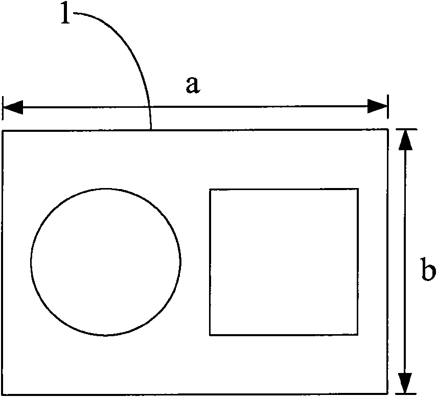
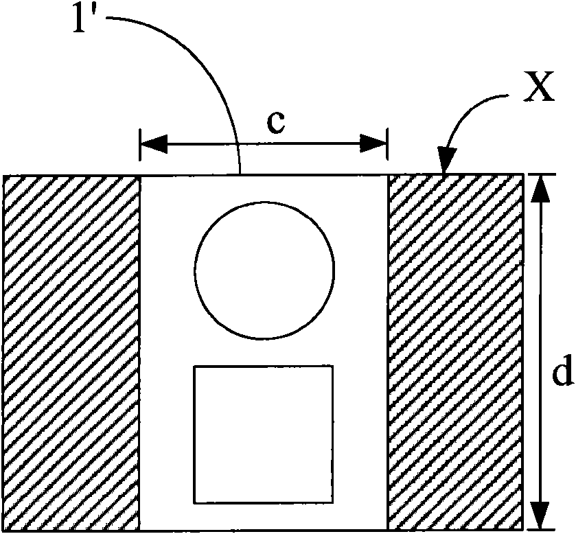
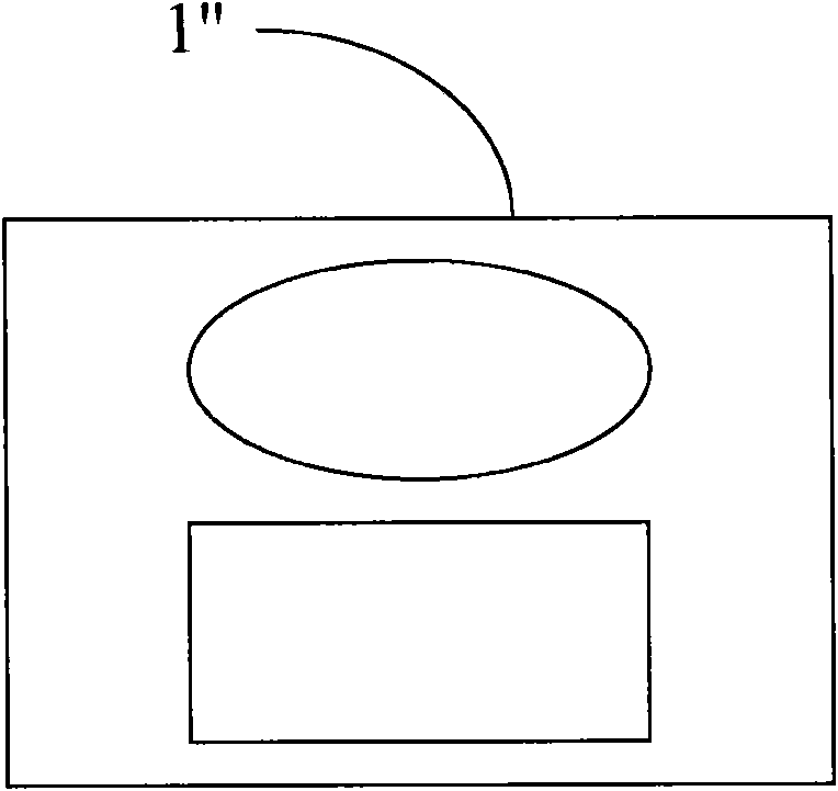
technical field [0001] The present invention relates to an imaging component, especially an imaging component arranged on a projection system to selectively project images with a proper display ratio. Background technique [0002] With the advancement of information technology, the amount of digital data is increasing rapidly, and digital devices for displaying digital data are also booming. Among them, since the projection system receives digital data input from an external digital device, and projects an enlarged image after processing, the digital data is clearer and easier to see, and it can be used in some situations (such as projecting video games) or movie images) to provide richer entertainment effects, so it has become a display device commonly used in digital devices. [0003] Generally speaking, the display specification of digital data is often set to a specific display size ratio. Specifically, the display ratio of the digital data (that is, the ratio of the h...

Claims


Application Information

Patent Timeline
IPC IPC(8): G03B21/14G03B21/28G02B7/02G02B17/08
Inventor 林宏英
Owner DELTA ELECTRONICS INC
Why Eureka
Try Eureka