Supercharge Your Innovation With Domain-Expert AI Agents!

Curved part of endoscope

A technology for endoscopes and bending parts, which is applied in the field of bending parts, can solve problems such as difficulty in improving the processing accuracy of convex parts, difficulty in rotating smoothly, and inability to fully and smoothly bend the bending part, so as to achieve low-cost manufacturing, reduce manufacturing costs, The effect of linking the simple process

Inactive Publication Date: 2010-03-24
OLYMPUS CORP
View PDF2 Cites 28 Cited by
  • Summary
  • Abstract
  • Description
  • Claims
  • Application Information

AI Technical Summary

Problems solved by technology

[0004] In the bending part of Japanese Publication No. 61-21042, since the embedded piece extending along the axis direction of the joint ring is embedded into the locked part swingably along the connecting surface of the joint ring, the two joints connected The ring is difficult to turn smoothly, and the bending part cannot be fully and smoothly bent
[0005] In addition, in the bending portion of Japanese Patent Application Laid-Open No. 2001-104239, it is difficult to improve the processing accuracy of the convex portion, and it is difficult to form a curved portion between the convex portion and the through hole. Appropriate clearance, the same as the bending part of Japanese National Publication Publication No. 61-21042, the two connected rings are difficult to rotate smoothly, and the bending part cannot be fully and smoothly bent

Method used


Image

  • Curved part of endoscope
  • Curved part of endoscope
  • Curved part of endoscope

Examples


Embodiment Construction

[0029] Hereinafter, various embodiments of the present invention will be described with reference to the drawings.

[0030] Figure 1 to Figure 4 The first embodiment of the present invention is shown.

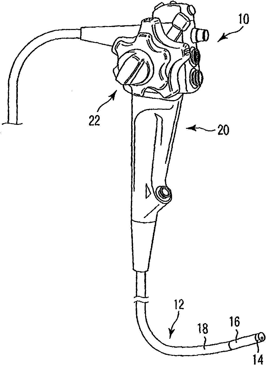
[0031] refer to figure 1 , the endoscope 10 has an elongated insertion portion 12 that can be inserted into a body cavity. In the insertion portion 12 , a distal rigid portion 14 , a bendable bending portion 16 , and a vertically long and flexible flexible tube portion 18 are arranged in this order from the distal end side. The operation part 20 which can be grasped and operated by an operator is connected to the base end part of the insertion part 12. As shown in FIG. A bending operation knob 22 for bending and operating the bending portion 16 is disposed on the operating portion 20 .

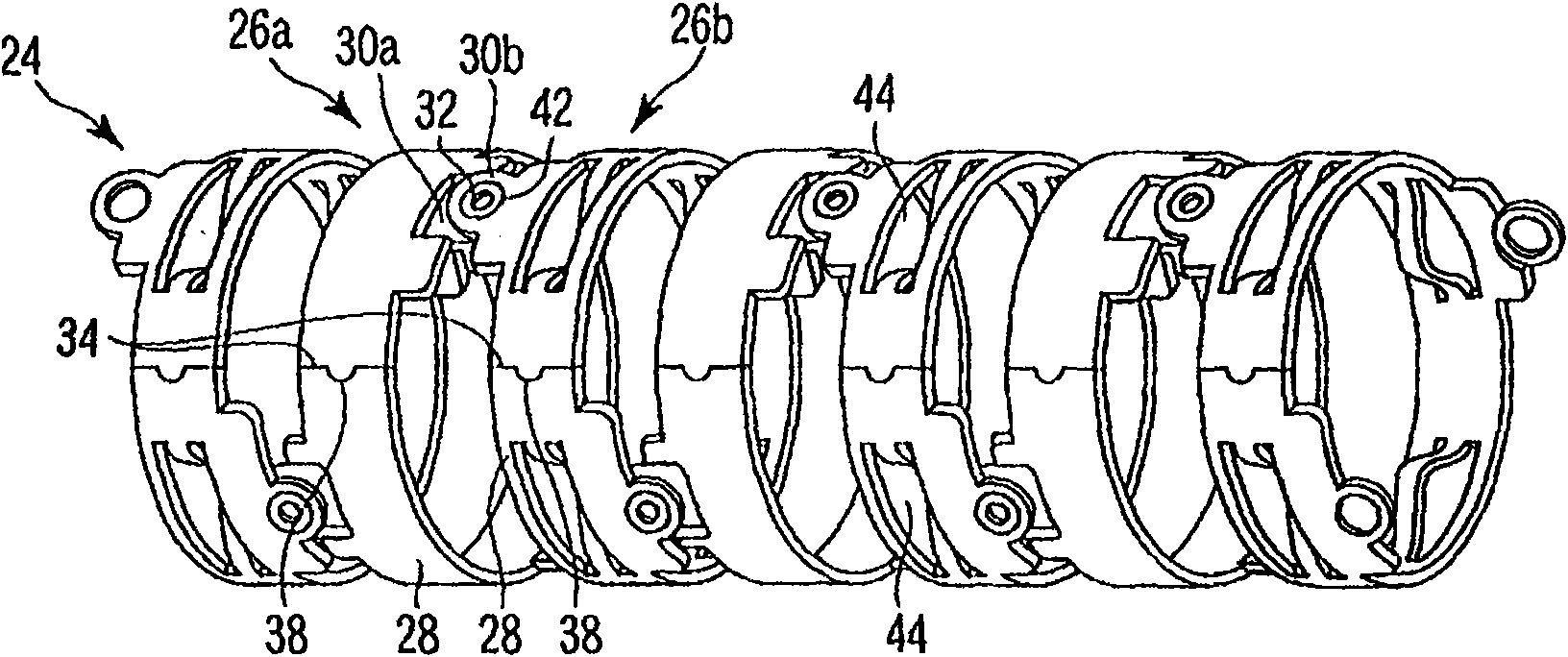
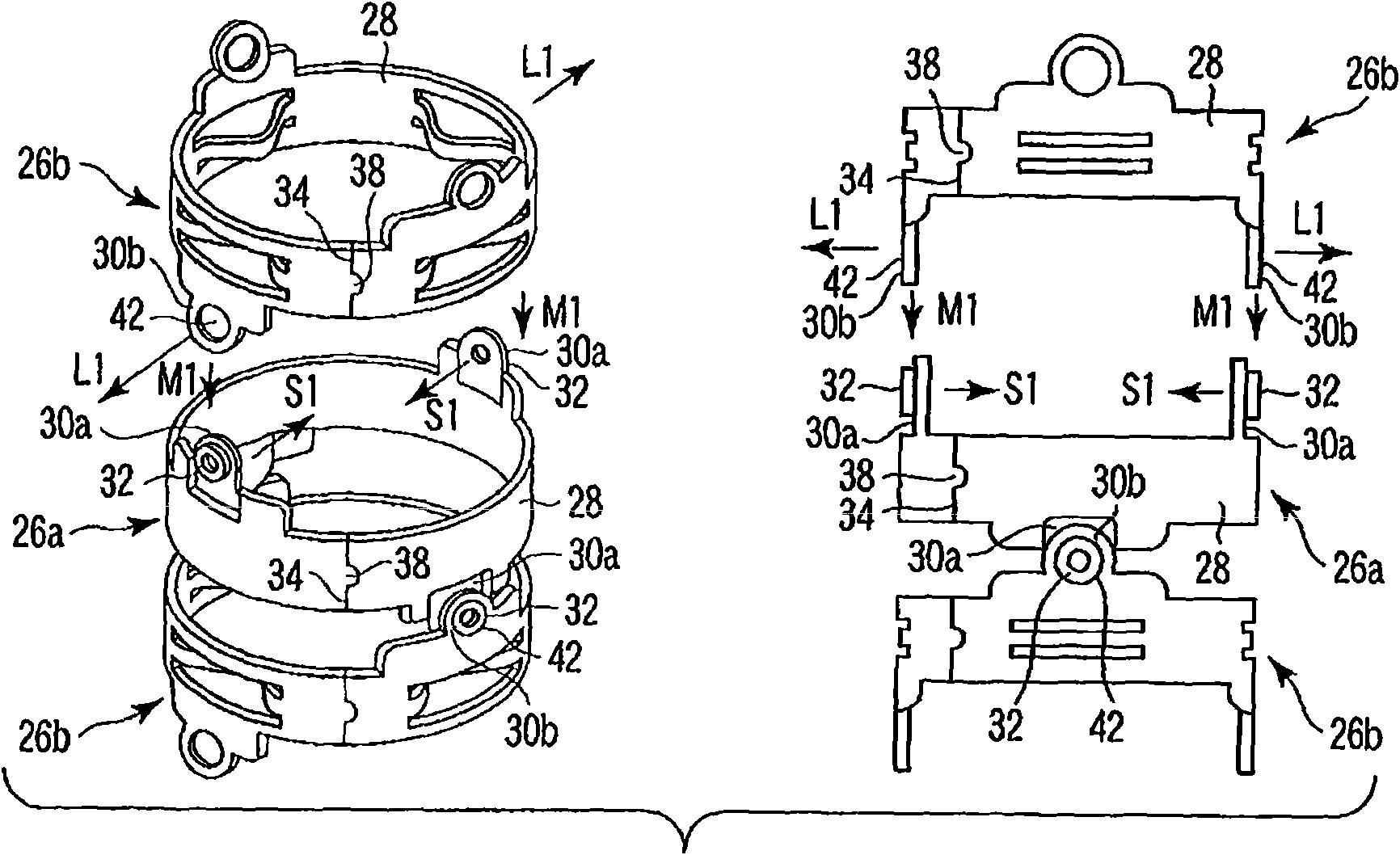
[0032] refer to figure 2 The cylindrical curved pipe 24 forming the skeleton of the curved portion 16 will be described.

[0033] In this bent pipe 24 , two types of nodal rings, namely...


PUM


Abstract

Provided is a curved part of an endoscope which is provided at the insertion portion of the endoscope and which can perform smooth bending operation and easily manufactured. The curved part comprisesnodal rings (26a, 26b) each having a cylindrical part (28) and coaxially arranged parallel with each other. One ring (26a) of the adjacent both nodal rings (26a, 26b) has a projection (32) formed integrally with the cylindrical part (28) and extending in the radial direction of the cylindrical part (28). The other ring (26b) of the adjacent both nodal rings (26a, 26b) has a reception part (42) which is formed integrally with the cylindrical part (28) and into which the projection (32) is inserted rotatably around the longitudinal axis of the projection (32). Each of the nodal rings (26a, 26b)has, in its cylindrical part (28), an unjoined or joined discontinuous part (34) extending so as to cross the circumferential direction of the cylindrical part (28).

Description

technical field [0001] The present invention relates to an insertion part of an endoscope and a bending part capable of bending. Background technique [0002] The endoscope has an elongated insertion portion capable of being inserted into a body cavity, and a bending portion capable of bending is arranged at a distal end portion of the insertion portion. In this bent portion, a plurality of cylindrical node rings are rotatably and coaxially connected to each other. As a method of connecting the link rings, for example, riveting is used. That is, a pair of tongues protrudes from both ends of the cylindrical portion of the node ring symmetrically to the center axis, and the tongues of two adjacent node rings overlap each other and are rotatably riveted and fixed. Especially for small-diameter endoscopes, it is very troublesome to adopt this fastening method of riveting. [0003] A connection method that does not use riveting is disclosed in Japanese Patent Application Publi...

Claims


Application Information

Patent Timeline
Patent Type & Authority Applications(China)
IPC IPC(8): A61B1/00G02B23/24
CPCG02B23/2407A61B1/0055
Inventor 北川英哉
Owner OLYMPUS CORP
Features
  • R&D
  • Intellectual Property
  • Life Sciences
  • Materials
  • Tech Scout
  • Unparalleled Data Quality
  • Higher Quality Content
  • 60% Fewer Hallucinations
Learn More