Navigation device

A technology of navigation device and installation location, applied in navigation, measurement device, mapping and navigation, etc., can solve the problems of narrow side of disassembly and assembly unit, smaller display area, not necessarily visual recognition, etc., to prevent inadvertent falling off, improve The effect of disassembly and assembly

Inactive Publication Date: 2010-03-24
HONDA ACCESS CORP
View PDF0 Cites 6 Cited by
  • Summary
  • Abstract
  • Description
  • Claims
  • Application Information

AI Technical Summary

Problems solved by technology

[0007] In the case of the device described in Patent Document 1, since the display arranged on the detachable unit is configured to be foldable, it needs to be folded every time it is attached to or detached from the vehicle-side unit, which is extremely cumbersome.
[0008] In the case of the device described in Non-Patent Document 1, the display is fixed on the side of the detachable unit, thus avoiding the above-mentioned problems. However, since the side of the detachable unit is narrow compared with the detachable surface of the vehicle side unit, the area of ​​the display is reduced as a result. Smaller, may not be able to meet the visual recognition

Method used


Image

  • Navigation device
  • Navigation device
  • Navigation device

Examples


Embodiment 1

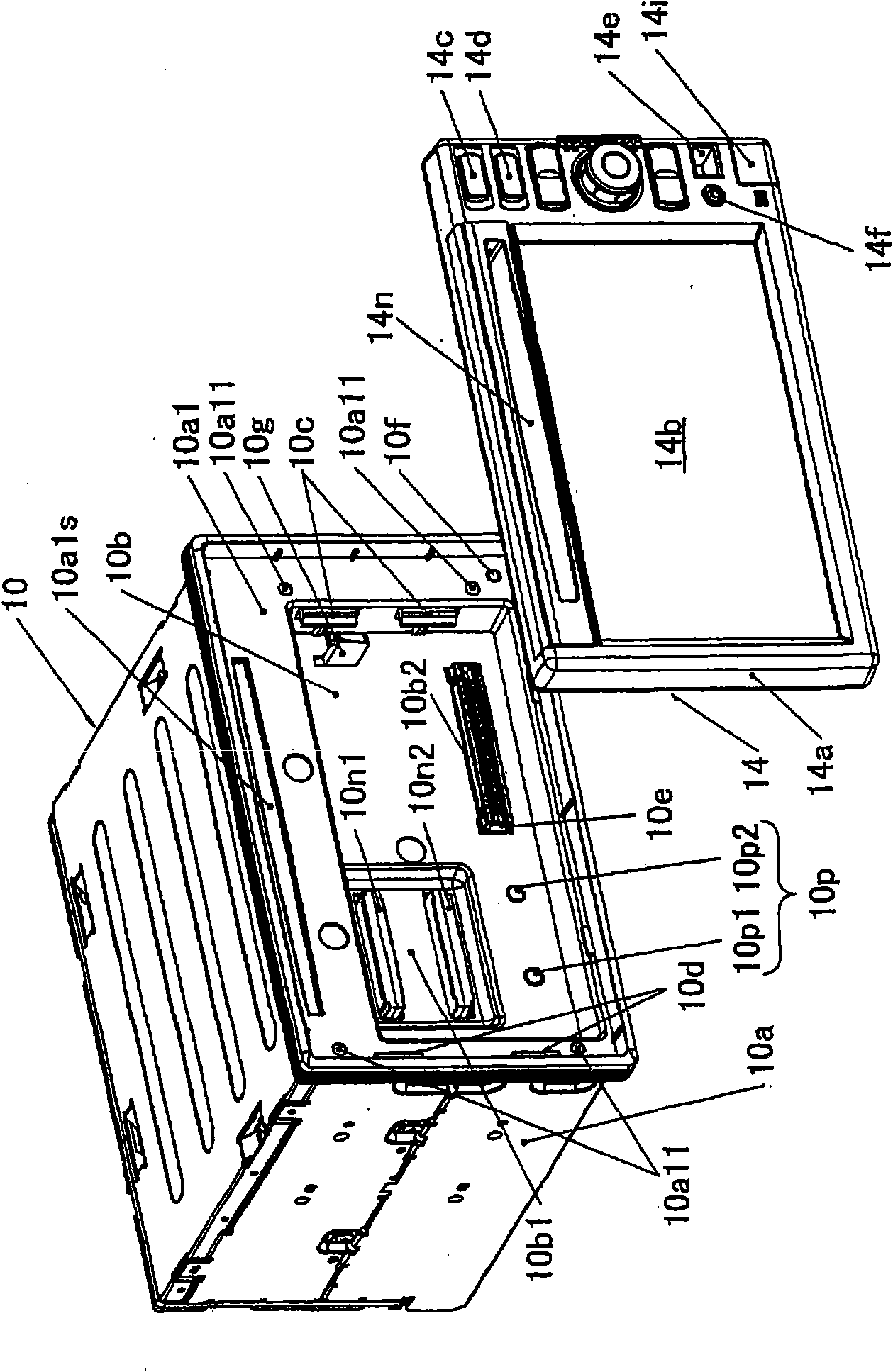
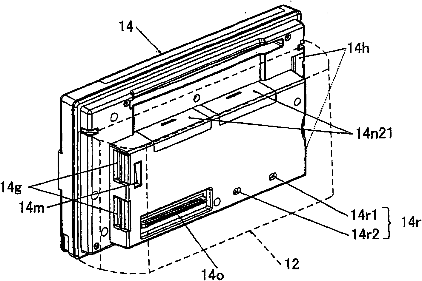
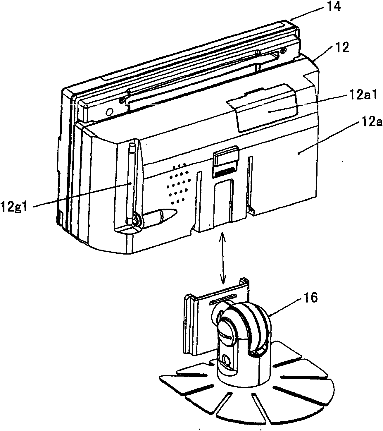
[0084] figure 1 It is a perspective view of the front side of the basic unit and the front panel unit in the navigation device of the first embodiment of the present invention, figure 2 Is a perspective view of the back side of the front panel unit, image 3 It is a perspective view of the front panel unit (rear side), bracket unit, and bracket unit mounting arm. Figure 4 It is an explanatory diagram showing the state of mounting it on the vehicle, Figure 5 (a) is an explanatory diagram of the driver's seat of the vehicle, Figure 5 (b) It is a side view near the steering wheel. Image 6 and Figure 7 It is a cross-sectional view of the base unit 10 and the front panel unit 14 when viewed from above, Figure 8 and Picture 9 It is a partial cross-sectional view when viewing the base unit 10 and the front panel unit 14 from the right side, Picture 10 (a), (b), (c) are explanatory diagrams of the front panel unit 14.

[0085] As shown in the figure, the navigation device of the em...

Embodiment 2

[0209] Figure 31 It is a perspective view showing a state where the navigation device of the second embodiment of the present invention is mounted on a vehicle, Figure 32 From Figure 31 The front view of the state with the front panel unit 14 removed, Figure 33 for Figure 32 Illustrated cross-sectional view.

[0210] With Figure 5 and Picture 11 The different points of the first embodiment shown are focused on the description. In the second embodiment, such a structure is adopted: Figure 32 As shown, the base unit 10 is housed in a manner that is completely built into the inside of the rectangular recessed portion 24 formed on the dashboard D, and when the front panel unit 14 is installed, such as Figure 31 As shown, the front panel unit 14, more specifically, the upper part of the front panel unit housing 14a protrudes from the wall surface Dw of the instrument panel D.

[0211] That is, it is configured such that the base unit 10 is freely fixed to the dashboard D of the d...

Embodiment 3

[0225] Figure 34 It is a perspective view showing a state where the navigation device of the third embodiment of the present invention is mounted on a vehicle, Figure 35 It is the front view when the front panel unit 14 is removed from this state, Figure 36 with Figure 37 The same is a perspective view of the state mounted on the vehicle, Figure 38 Yes means Figure 34 An explanatory diagram of the relationship between the front panel unit 14, the base unit 10, the instrument panel D, and the upper cover described later.

[0226] The description will focus on the differences from the previous embodiment. In the third embodiment, Figure 34 In the side view shown, it is formed on the gently inclined instrument panel D Figure 35 The inside of the accommodating portion 38 shown accommodates the base unit 10, and even the base unit 10, more specifically, the vicinity of the opening of the base unit housing 10a is surrounded by a decorative panel 40.

[0227] The open end of the dec...


PUM


Abstract

A navigation device has a base unit (10) fixable to a dashboard (D) of the driver seat of a vehicle, a front panel unit (14) detachably attachable to the base unit and having a display (14b) for displaying map data, and a microcomputer having a navigation function for causing the located vehicle position to be displayed on the map data. When the front panel unit (14) is at an installation positionwhere it is installed on the base unit (10), a portion of the front panel unit (14) projects, in a side view, in the direction toward a user at the driver seat from a surface (Dw) of the dashboard (D). Thus, the front panel unit can be more flexibly attached to and detached from the base unit without sacrificing the external appearance of the navigation device.

Description

Technical field [0001] The present invention relates to a navigation device, and more specifically, to a device that is mounted on a vehicle and conveys information (direction, map, route, etc.) for reaching a destination to a driver. Background technique [0002] The above-mentioned navigation device was originally limited to the type that is integrally fixed to the vehicle, but recently, a portable type that can be moved has been proposed, and a separate navigation device that can only be disassembled and assembled for the navigation function has been proposed to further improve the convenience of use. Device (for example, refer to Patent Document 1 and Non-Patent Document 1). [0003] The technology described in Patent Document 1 is a navigation device that includes a GPS receiver connected to a GPS antenna, a gyro sensor, and a vehicle signal processing circuit for vehicle speed signals, a display that displays a map, and a device that controls the whole ECU composition. In th...

Claims


Application Information

Patent Timeline
Patent Type & Authority Applications(China)
IPC IPC(8): B60R11/02G01C21/00
CPCB60R11/0258B60R2011/0294G01C21/3688B60R2011/0047B60R11/0235B60R2011/0078B60R11/02B60R2011/0075B60R2011/0007G01C21/26G01C21/265B60R2011/0005
Inventor 增田浩朗德江纯山本和广绵贯修一高桥芳典小暮勤大石康夫须崎之彦细贝俊明
Owner HONDA ACCESS CORP
Why Eureka
Try Eureka