Anesthesia evaporator

An anesthesia vaporizer and vaporization chamber technology, applied in the field of anesthesia vaporizers, can solve the problems of occupying the external space of the vaporizer, unable to change the temperature of the vaporizer, complex structure and assembly, etc.

Active Publication Date: 2010-03-31
SHENZHEN MINDRAY BIO MEDICAL ELECTRONICS CO LTD
View PDF0 Cites 36 Cited by
  • Summary
  • Abstract
  • Description
  • Claims
  • Application Information

AI Technical Summary

Problems solved by technology

[0007] However, this kind of anesthesia evaporator generally has the following disadvantages: 1) Although there is a temperature compensation unit, since the temperature compensation unit and the pressure compensation unit are independent of each other, the temperature compensation unit cannot change the temperature of the evaporator, and the pressure compensation unit cannot change the temperature of the evaporator during use. The unit does not regulate the temperature, and the two cannot be combined. As a result, during the use of the evaporator, the temperature of the evaporator will gradually decrease with the increase of time, and the evaporation speed of the anesthetic agent will also slow down. The deviation between the concentration of the anesthetic vapor and the set concentration increases; 2) When the pressure compensation unit is placed outside the evaporator, it occupies the external space of the evaporator, making the structure of the evaporator not compact enough; when the pressure compensation unit is placed inside the evaporator, Due to the need to mix and assemble with other units, the structure and assembly are complicated

Method used


Image

  • Anesthesia evaporator
  • Anesthesia evaporator
  • Anesthesia evaporator

Examples


Embodiment Construction

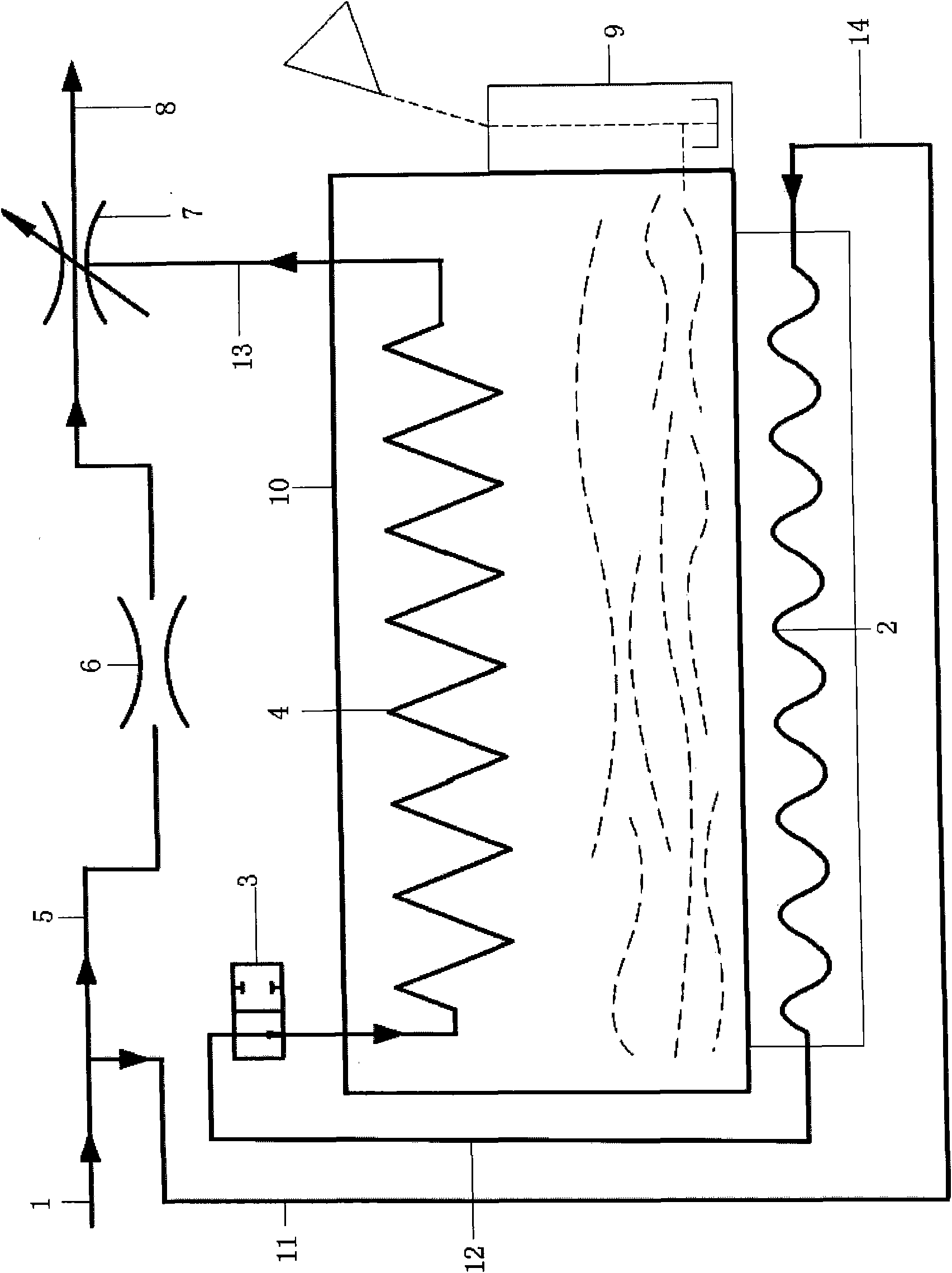
[0021] Such as Figure 2 to Figure 5 As shown, the anesthesia vaporizer in this embodiment includes a fresh gas inlet 1 , a mixed gas outlet 8 , an evaporation chamber 10 , a dosing unit 9 , a first gas branch 5 and a second gas branch 14 . Fresh gas inlet 1 is used to receive fresh gas. The mixed gas outlet 8 is used to output the mixed gas of fresh gas and anesthetic vapor. The evaporation chamber 10 can be made of metal with good thermal conductivity, and the evaporation chamber 10 has a cavity for storing anesthetics. The dosing unit 9 is used for perfusing anesthetic agent into the cavity of the evaporation chamber 10, and the dosing unit 9 communicates with the cavity through a channel.

[0022] The first gas branch 5 is provided with a temperature compensation unit 6 and a concentration control unit 7 . The temperature compensation unit 6 is equivalent to a valve body that can change the vent diameter of the first gas branch 5, and it adjusts the vent diameter of the...


PUM


Abstract

The invention discloses an anesthesia evaporator, comprising a fresh gas inlet, a mixed gas outlet, a first gas branch, a second gas branch and an evaporation chamber; wherein the evaporation chamber is provided with a cavity containing anesthetic, the first gas branch is connected with the fresh gas inlet and the mixed gas outlet, the second gas branch comprises a first gas passage, a pressure compensation unit, a second gas passage, a medication core unit and a third gas passage, wherein the pressure compensation unit is provided with a curve continuous closed aeration channel, the medication core unit is provided with a soaking part directly contacted with anesthetic in the cavity, the fresh gas inlet, the first gas passage, the aeration channel, the second gas passage, the medication core unit, the third gas passage and the mixed gas outlet are connected in sequence, the pressure compensation unit is arranged in the cavity and provided with a heat conductor which is directly contacted with anesthetic for heat transmission, and the aeration channel is opened on the heat conductor. The anesthesia evaporator can realize stable output of concentration of anesthetic steam in mixed gas.

Description

technical field [0001] The invention relates to an anesthetic vaporizer. Background technique [0002] The anesthesia vaporizer is a device that can effectively evaporate the anesthetic solution and accurately input the anesthetic into the anesthesia breathing circuit at a certain concentration. It can eliminate the influence of temperature changes, pressure changes and other factors on its concentration output. [0003] Such as figure 1 As shown, the anesthesia vaporizer generally includes a fresh gas inlet 1', a pressure compensation unit 2', a fresh gas control valve 3', a drug core unit 4', a bypass 5', a temperature compensation unit 6', a concentration control unit 7', Mixed gas outlet 8', dosing unit 9' and evaporation chamber 10'. Fresh gas inlet 1', bypass 5', temperature compensation unit 6', concentration control unit 7' and mixed gas outlet 8' are connected in sequence; fresh gas inlet 1', pressure compensation unit 2', fresh gas control valve 3' , the drug co...

Claims


Application Information

Patent Timeline
Patent Type & Authority Applications(China)
IPC IPC(8): A61M16/01
CPCA61M2205/3372A61M16/183A61M16/18
Inventor 陈冬华龚道明王炜
Owner SHENZHEN MINDRAY BIO MEDICAL ELECTRONICS CO LTD
Why Eureka
Try Eureka