
Rotary compressor

A technology of rotary compressor and compression chamber, applied in rotary piston machinery, rotary piston pump, rotary piston/oscillating piston pump components, etc., can solve problems such as pressure leakage of compression chamber, and prevent pressure leakage Effect

Inactive Publication Date: 2010-03-31
SAMSUNG ELECTRONICS CO LTD
View PDF4 Cites 5 Cited by
  • Summary
  • Abstract
  • Description
  • Claims
  • Application Information

AI Technical Summary

Problems solved by technology

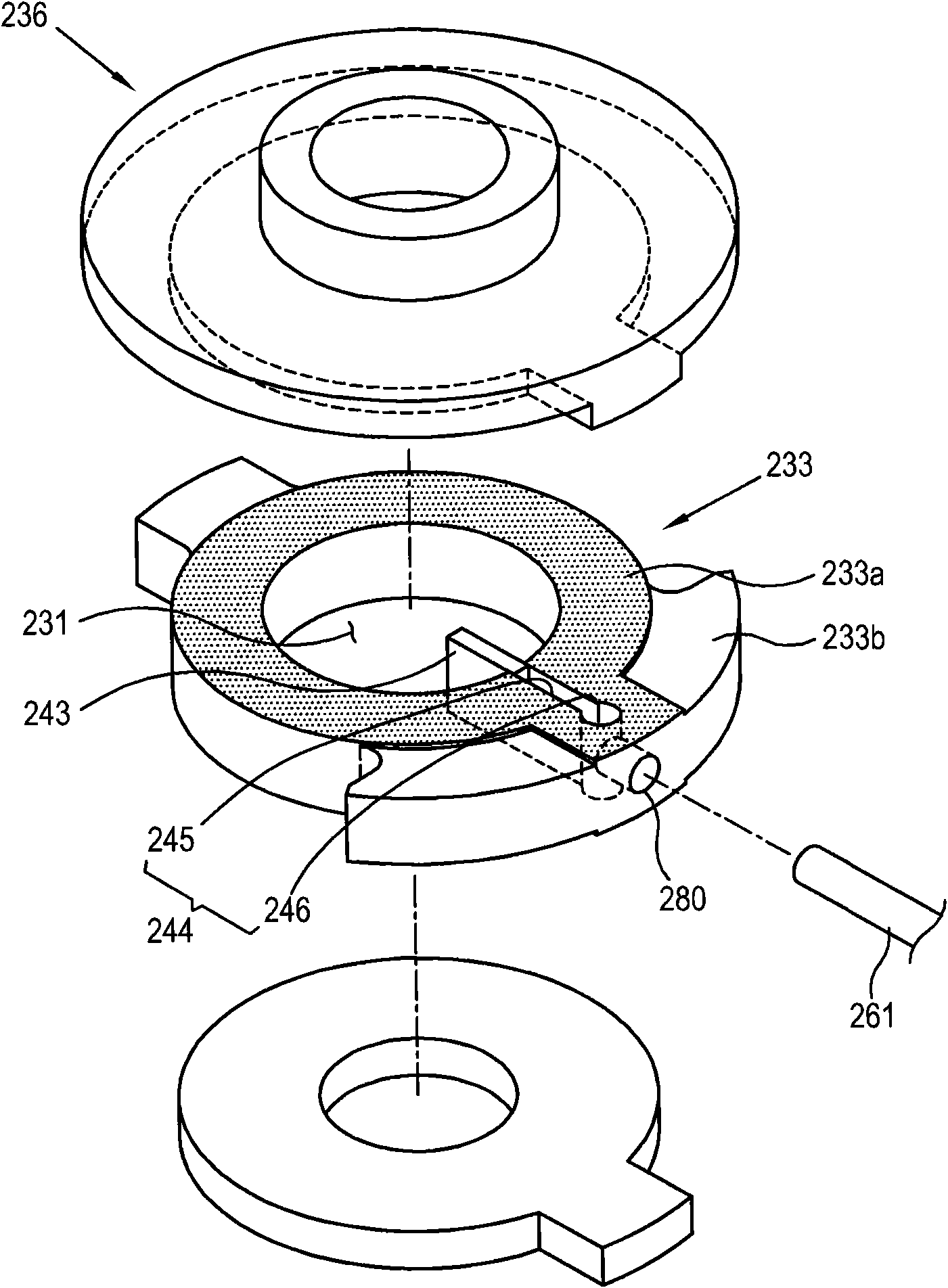
[0006] However, in such a conventional rotary compressor, since the communicating portion 280 penetrates from the outer surface of the compression chamber forming portion 233 a to the airtight chamber along the advancing and retreating direction of the blade 243 , the process of pressing the connecting pipe 261 into the communicating portion 280 In this case, a gap may be formed between the contact surface of the cylinder 233 and the flange part 236 due to the deformation of the cylinder, and thus there is a possibility that the pressure of the compression chamber 231 may leak through the gap.

Method used


Image

  • Rotary compressor
  • Rotary compressor
  • Rotary compressor

Examples


Embodiment Construction

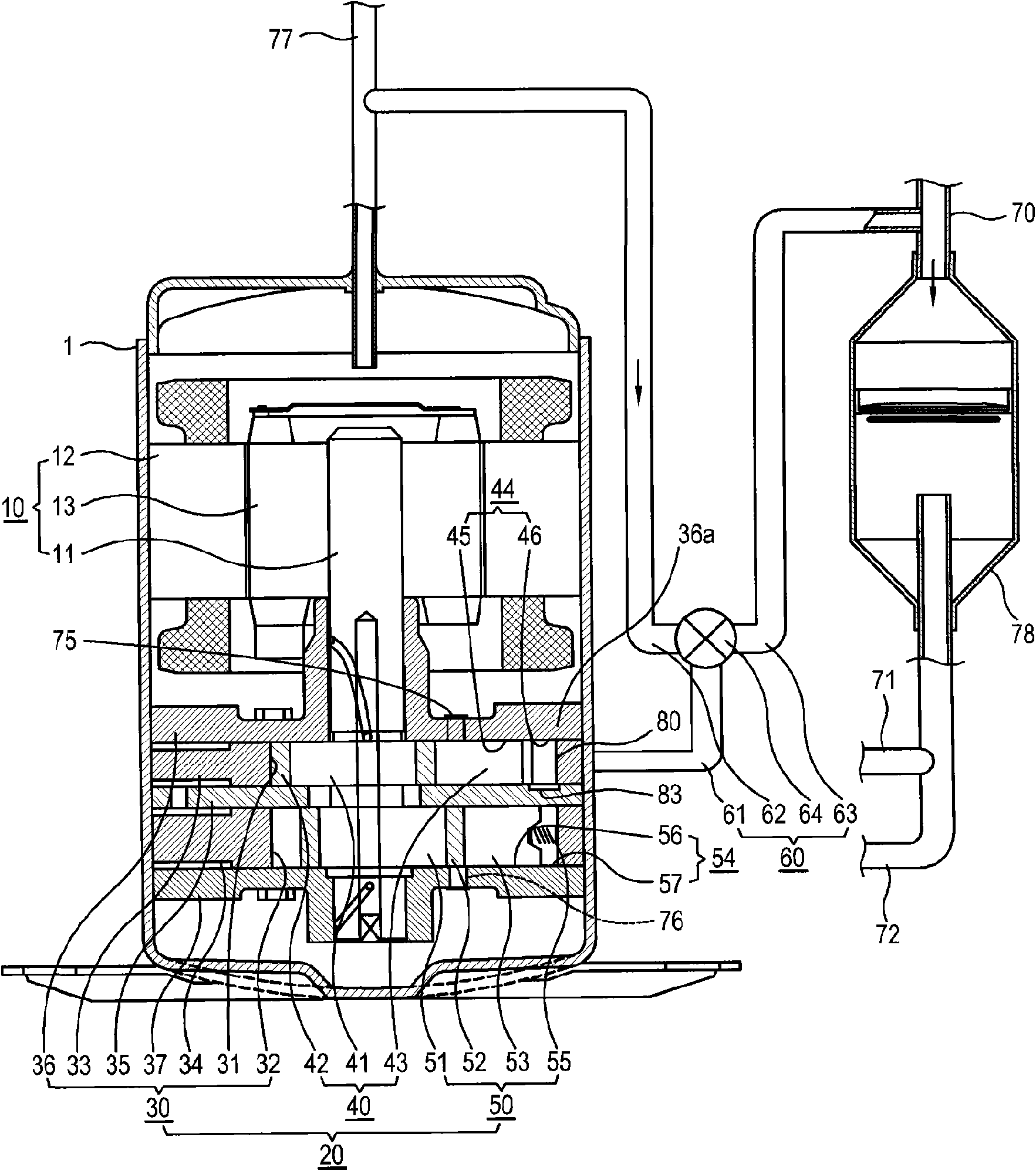
[0030] Below, refer to Figure 2 to Figure 7 A first embodiment of the rotary compressor according to the present invention will be described in detail.

[0031] like figure 2 As shown, the rotary compressor according to this embodiment has a casing 1 forming an appearance, an electric mechanism 10 disposed on the inner upper portion of the casing 1 , and an electric mechanism 10 disposed on the inner lower portion of the casing 1 and connected to the electric mechanism 10 through a rotating shaft 11 The compression mechanism 20.

[0032] The motor mechanism 10 includes a cylindrical stator 12 provided inside the casing 1 , and a rotatable rotor 13 provided inside the stator 12 and coupled to the rotating shaft 11 at its center. The motor mechanism 10 drives the compression mechanism 20 connected via the rotating shaft 11 according to the rotation of the rotor 13 when the power is turned on.

[0033] The compression mechanism 20 has: a cylinder unit 30 formed with mutually...


PUM


Abstract

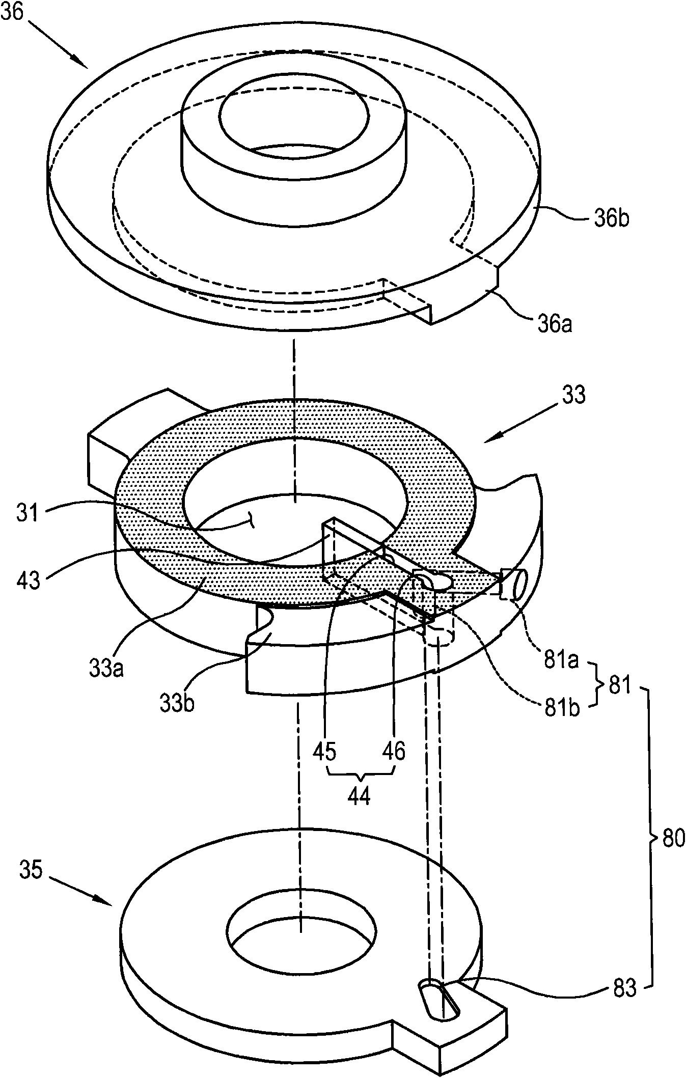
The invention provides a rotary compressor, comprising a housing; a cylinder with a compression chamber and a blade groove, wherein the blade groove is composed of, a blade guide part formed by makingan outward depression of the inner wall of the compression chamber, and an enclosed chamber arranged outside the blade guide part and having a width that is more than that of the blade guide part bya predetermined expansion width; blades capable of moving forwards and backwards along the blade groove and simultaneously partitioning the compression chamber; a flange part for sealing the upper andlower openings of the cylinder; and a communication part, which passes through the outer side surface of the cylinder and extends to the enclosed chamber along the direction different from the movingdirection of the blades, for providing high pressure or low pressure for the enclosed chamber. Thus, the rotary compressor of the invention can enable the deformation of the parts to be minimized, thereby preventing the pressure leakage of the compression chamber.

Description

technical field [0001] The present invention relates to a rotary compressor, in particular to a variable capacity rotary compressor capable of preventing pressure leakage in a compression chamber. Background technique [0002] Generally, a compressor is used as a device for compressing a compressed medium and is applied to refrigeration devices such as air conditioners and refrigerators. Recently, in order to be able to change the cooling capacity, and to save energy while performing optimal cooling that meets the required conditions, a variable capacity rotary compressor that can change the compression capacity of the refrigerant is being developed. [0003] This variable capacity rotary compressor includes: a casing forming an appearance; a cylinder forming a compression chamber; a flange closing the upper and lower openings of the cylinder; a rotating shaft having an eccentric portion rotating inside the compression chamber; The roller that is rotatably arranged outside ...

Claims


Application Information

Patent Timeline
IPC IPC(8): F04C18/34
CPCF04C18/356F04C23/008F04C28/24F04C29/0028F04C29/124F04C2210/26F04C2240/40Y10S415/00Y10S417/902
Inventor 杨珉洙李祯培徐钟天金垠锡韩敬俊成春模
Owner SAMSUNG ELECTRONICS CO LTD
Learn More