

Pressurization test device for cladding tube
A pressurized test and cladding tube technology, applied in the field of testing, can solve problems such as threats to safe operation of nuclear power plants, pressure rise, etc., and achieve the effects of avoiding explosion hazards, improving accuracy, and avoiding pressure leakage
- Summary
- Abstract
- Description
- Claims
- Application Information
AI Technical Summary
Problems solved by technology
Method used
Image

Examples
Embodiment Construction
[0030] Embodiments of the invention are described in detail below, examples of which are illustrated in the accompanying drawings. The embodiments described below by referring to the figures are exemplary and are intended to explain the present invention and should not be construed as limiting the present invention.
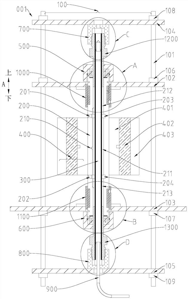
[0031] Such as Figure 1-Figure 5 As shown, the pressure test device 001 for a cladding tube according to an embodiment of the present invention includes a test rack 100, a test tube 200, a first sealing member 500, a second sealing member 600, a third sealing member 700 and a fourth sealing member 800 .
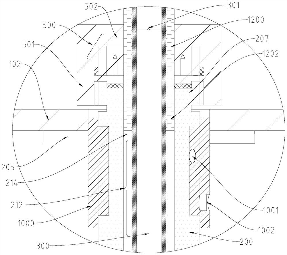
[0032] Such as Figure 1-Figure 3 As shown, the cladding tube 300 has a first end 303 and a second end 304 opposite along its length. The test tube 200 is set on the test frame 100 and can be sleeved on a part of the cladding tube 300 . The test tube 200 has a first end 207 and a second end 208 opposite to each other along its length direction. A first port...
PUM
 Abstract
Description
Claims
Application Information