Cooling device for cooling a metal strip

A technology of cooling device and metal strip, applied in the direction of workpiece cooling device, metal rolling, metal rolling, etc., can solve the problems of low efficiency of cooling device, small cooling area, uneconomical, etc., and achieve good heat exchange effect

Active Publication Date: 2010-03-31
SMS DEMAG AG
View PDF1 Cites 7 Cited by
  • Summary
  • Abstract
  • Description
  • Claims
  • Application Information

AI Technical Summary

Problems solved by technology

The energy available for the radial acceleration of the particles is therefore rather limited, which leads to the fact that the radial discharge of the cooling medium opposite to the running direction of the metal strip takes place only over a limited length or area, which again resulting in a correspondingly very small cooling area
In this regard the cooling device is inefficient and uneconomical in the prior art

Method used


Image

  • Cooling device for cooling a metal strip
  • Cooling device for cooling a metal strip
  • Cooling device for cooling a metal strip

Examples


Embodiment Construction

[0024] The invention will be described in detail below in the form of an embodiment with reference to the above-mentioned drawings.

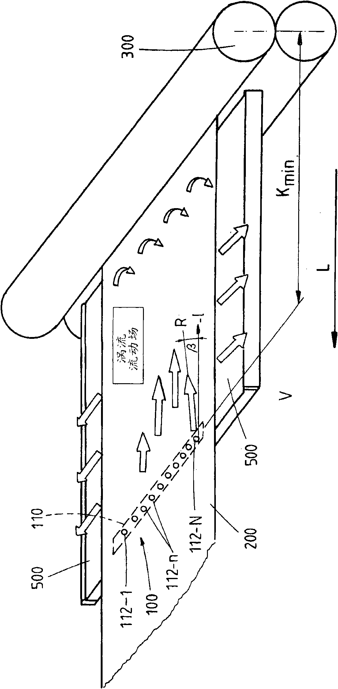
[0025] figure 1 The discharge end of a cold rolling stand 300 with a metal strip 200 running to the left is shown. A panel 500 is arranged under the metal strip in the form of a ledge. At the distance K from the cold rolling stand min A nozzle beam 110 with a plurality of nozzles 112 is arranged in the guide table crossing the running direction of the metal strip.

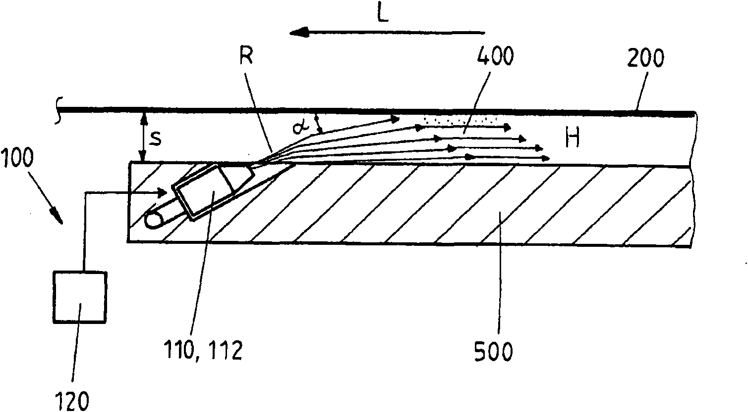
[0026] figure 2The arrangement of the nozzles 112 or the nozzle bar 110 in the guide table 500 is shown. In particular, it can be clearly seen that the nozzles are arranged in the guide table in such a way that it sprays the cooling medium 400 at a sharp spray angle α opposite to the running direction L of the metal strip onto the back side of the metal strip. By contact with the metal strip 200 running in the opposite direction L, shear forces act on the participating particle...


PUM


Abstract

The invention relates to a cooling device (100) for cooling a metal strip (200) following reshaping in a cold rolling stand (200) having at least one nozzle (112) for spraying a cooling medium (400) onto the surface of the metal strip (200). In order to make such known cooling devices more effective and more efficient, the invention proposes providing a plate (500) which, in an operational position, is arranged parallel to the surface of the metal strip (200) at the outlet of the cold rolling stand (300), and proposes arranging the nozzle in the operation position in such a way that the cooling medium is sprayed at an acute spray angle a into a cavity between the surface of the metal strip and the opposite plate with a spray direction (R) counter to the running direction (L) of the metal strip.

Description

technical field [0001] The invention relates to a cooling device for cooling a metal strip after roll forming in a cold rolling stand. Background technique [0002] Such a device is basically known in the prior art, for example from Japanese patent document JP11129017A1. The cooling device disclosed in this document comprises a plurality of nozzles which are arranged below the metal strip to be cooled and from which coolant is sprayed each at right angles onto the back side of the metal strip from a common coolant groove. After the vertical impact on the back side, the coolant first leaves the back side of the metal strip radially or exits radially on the back side until it falls back from the back side of the metal strip into the coolant groove again at a certain distance from the nozzle. During radial discharge, a small number of sprayed coolant particles are discharged with a movement component along the running direction of the metal strip, while other particles are dis...

Claims


Application Information

Patent Timeline
Patent Type & Authority Applications(China)
IPC IPC(8): B21B45/02
CPCB21B45/0218B21B45/0233B21B1/28B21B1/36B21B45/02
Inventor D·马思韦斯H·帕维尔斯基H·-P·里克特F·吉塞勒H·泽茨舍S·塔默特
Owner SMS DEMAG AG
Why Eureka
Try Eureka