Core for rubber track and rubber track

A technology of rubber track and core iron, applied in the field of rubber track core iron and rubber track, to achieve the effect of smooth bending

Active Publication Date: 2010-03-31
FUKUYAMA GOMU KOGYO
View PDF6 Cites 0 Cited by
  • Summary
  • Abstract
  • Description
  • Claims
  • Application Information

AI Technical Summary

Problems solved by technology

[0007] In the rubber crawler C mentioned above, there is a problem that the steel

Method used


Image

  • Core for rubber track and rubber track
  • Core for rubber track and rubber track
  • Core for rubber track and rubber track

Examples


Embodiment Construction

[0081] Refer to Figure 1- Figure 8 , the embodiment of the present invention will be specifically described.

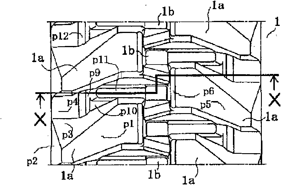
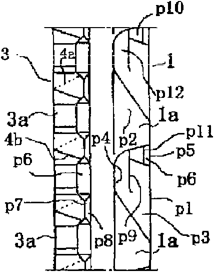
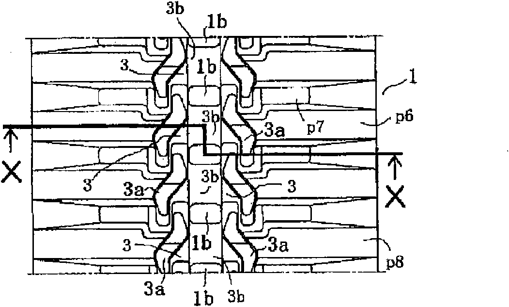
[0082] Fig. 1 shows rubber track of the present invention, Figure 1A is a diagram showing a part of the outer peripheral surface (ground plane), Figure 1B It is a figure showing a part of the circumferential direction viewed from the width direction of the rubber track, Figure 1C is a diagram showing a part of the inner peripheral surface, Figure 1D to indicate along Figure 1A and Figure 1C Sectional view of line X-X in.

[0083] In the drawings, numeral 1 denotes a rubber crawler of the present invention. This rubber crawler 1 is the same as the past rubber crawler C already described, and is wound on Figure 10B The circular track traveling device M shown is used between the driven wheel A and the driving wheel S, and consists of a belt body constituting a cycle of the rubber track main body 1a, a plurality of core irons 3 embedded in the belt body, an...


PUM


Abstract

A rubber track (1) has formed in it simple means that can carry a part of abnormal tensile force acting on substantially the entire length in the circumferential direction of the rubber track (1). Theconstruction secures smooth operation of the rubber track and reliably prevents cutting of a steel cord (s1) due to such abnormal tensile force. A core (3) has an engagement section (3b) located in the center region in the longitudinal direction of the core, guide projections (3a) on the outer sides of opposite ends in the longitudinal direction of the engagement section, and wing sections (3c) provided on the outer sides of the guide projections (3a). The core (3) further has tensile force carrying sections (4a, 4b) arranged at positions that are located in the thickness direction of the core and are closer to the outer periphery of the rubber track than the outer peripheral-side surfaces of the wing sections (3c). The tensile force carrying sections (4a, 4b) carry tensile force acting in the lateral direction of the core and also carry pressing force acting in the thickness direction of the core. Corresponding tensile force carrying sections (4a, 4b) of cores adjacent to each otherin the circumferential direction of the rubber track are engaged with each other. Further, a fixation belt layer in the circumferential direction of the rubber track is provided in a rubber track body(1a) at positions related to tensile force carrying sections (4a, 4b).

Description

technical field [0001] The present invention relates to a rubber crawler (circular track) and a core for a rubber crawler used to be attached to a circular track (crawler) traveling device of industrial vehicles represented by construction machinery, civil engineering machinery, agricultural work vehicles, transport vehicles, etc. iron. Background technique [0002] Fig. 12 is a side view showing a rubber track and a traveling device, Figure 13 It is a side view showing the periphery of the driving wheels of the traveling device. [0003] elephant Figure 12A As shown, in the conventional rubber crawler C, a row of tension reinforcing members is buried inside a rubber crawler main body h in the shape of an endless belt formed of a rubber elastic body or the like, and this is used as a tensile reinforcement layer s2, and the tension is reinforced. In the row, the steel cores s1 formed by twisting a plurality of steel wires as tensile reinforcements are arranged in a row al...

Claims


Application Information

Patent Timeline
IPC IPC(8): B62D55/253B62D55/24
CPCB62D55/205B62D55/24B62D55/26B62D55/253
Inventor 加藤祐作乘藤达哉
Owner FUKUYAMA GOMU KOGYO
Why Eureka
Try Eureka