

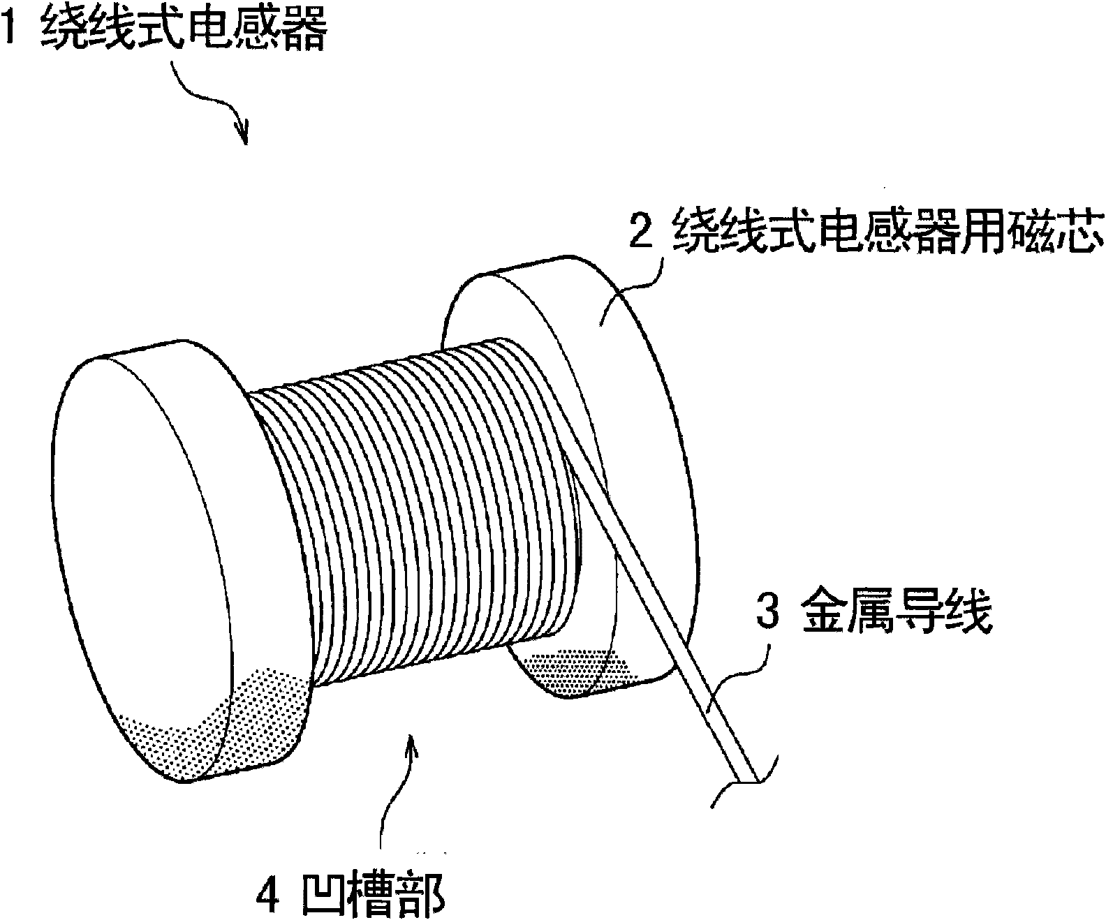
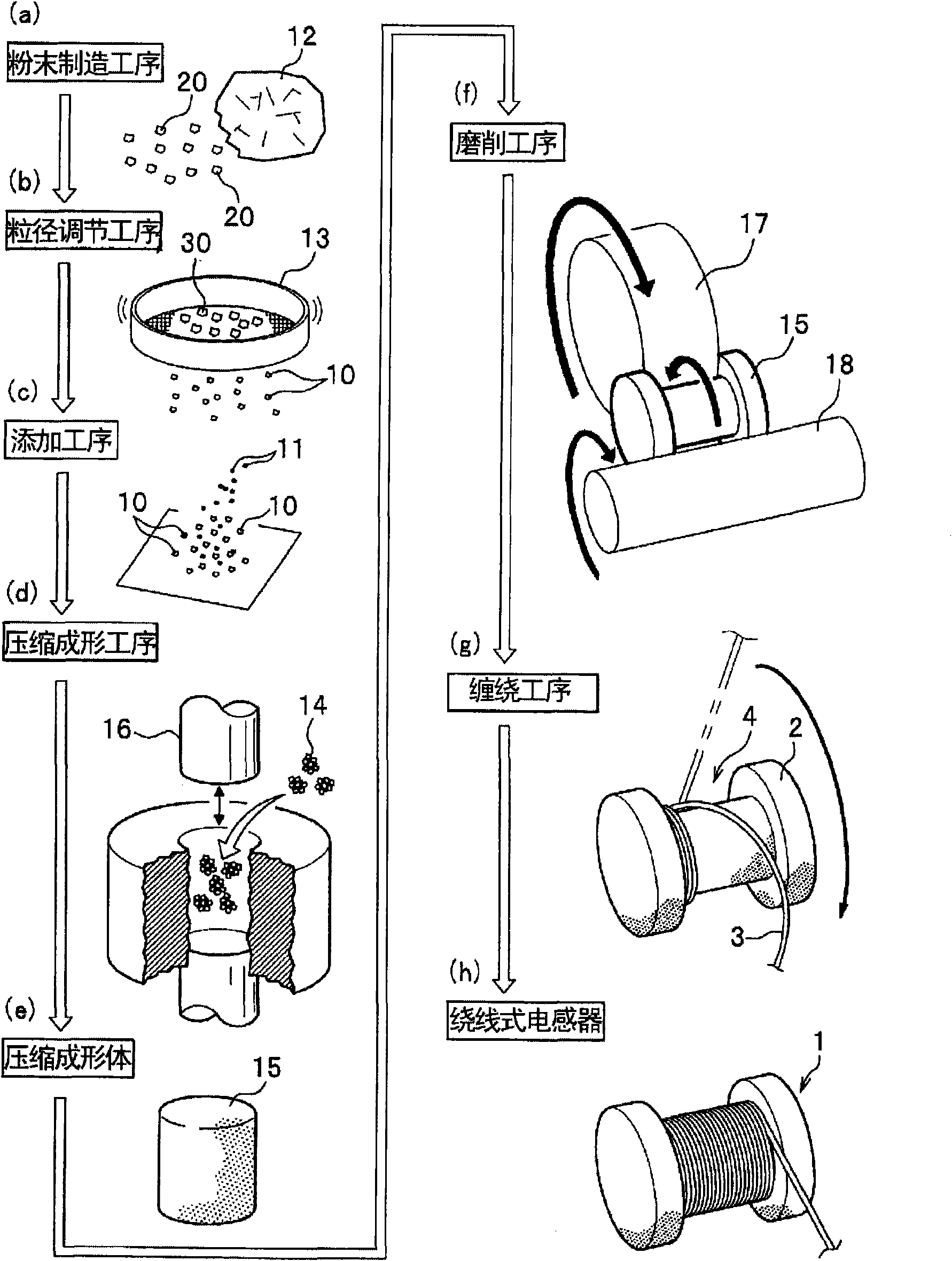
Winding inductor and process for manufacturing the same
A wire-wound inductor and manufacturing method technology, applied in inductor/transformer/magnet manufacturing, inductors, fixed inductors, etc., can solve the problems of small saturation magnetization value and difficult magnetic core, and achieve excellent DC overlap characteristics. Effect
- Summary
- Abstract
- Description
- Claims
- Application Information
AI Technical Summary
Problems solved by technology
Method used
Image

Examples
Embodiment 1
[0104] (1-1)
[0105] The magnetic core for a wire-wound inductor according to Example 1 will be described.
[0106] (Preparation of Magnetic Powder)
[0107] As the magnetic powder of Example 1, Fe—Si—Al alloy powder was used. The magnetic powder is obtained by heating and melting an alloy obtained by using Fe, Si, and Al as raw materials, coarsely pulverizing it with a jaw crusher, and finely pulverizing it with a ball mill for 90 minutes. Among them, the composition ratio of the Fe-Si-Al alloy powder, that is, the composition ratio of Fe:Si:Al, was 85:9.5:5.5.
[0108] (Adjustment of particle size of magnetic powder)
[0109] The particle size of all the Fe-Si-Al alloy powders was adjusted to be 75 μm or less by sieving the Fe—Si—Al alloy powders through a sieve with an opening of 75 μm (hereinafter referred to as magnetic powder 1A). In addition, unlike the magnetic powder 1A, in the particle size adjustment step, the magnetic powder 1B was also prepared which was fine...
Embodiment 2
[0140] Example 2 is an example of Fe-Si-Al-based alloy powder in which the composition ratio of the Fe-Si-Al-based alloy powder used in Example 1 was changed. In addition, the content of the magnetic powder having a particle size of 75 μm or less was also changed for each Fe—Si—Al alloy powder whose composition ratio was changed.
[0141] (Preparation of Magnetic Powder)
[0142] In Example 2, a magnetic body in which the composition ratio of the magnetic body powder 1A (the composition ratio of Fe:Si:Al of the Fe-Si-Al alloy powder is 85:9.5:5.5) used in Example 1 was changed was prepared. Powders 2A to 2F (see Table 3). In addition, the Fe-Si-Al alloy powder in Example 2 was obtained by mechanical pulverization similar to Example powder 1A.
[0143] 〔table 3〕
[0144] Magnetic powder
Composition ratio of Fe:Si:Al
89∶4∶7
88∶6∶6
Magnetic powder 2C
87∶8.5∶4.5
Magnetic powder 2D ...
Embodiment 3
[0163] In Example 3, the process of obtaining the Fe—Si—Al alloy powder as the magnetic powder 1A used in Example 1 was changed. That is, instead of using a magnetic powder obtained by mechanically pulverizing an alloy, a magnetic powder obtained by an atomization method was used. In addition, in Example 3 as well, Fe—Si—Al alloy powder having the same composition ratio as in Example 2 was prepared.
[0164] (Preparation of Magnetic Powder)
[0165] The Fe-Si-Al alloy powder is obtained by atomizing the Fe-Si-Al alloy, and its composition ratio is shown in Table 5 below.
[0166] 〔table 5〕
[0167] Magnetic powder
Composition ratio of Fe:Si:Al
Example Powder 3A
89∶4∶7
Example powder 3B
88∶6∶6
Example Powder 3C
87∶8.5∶4.5
Example Powder 3D
85∶9.5∶5.5
Example Powder 3E
84.5∶10∶5.5
Example powder 3F
83∶13∶4
[0168] (Adjustment of particle size of magnetic powder)
[0169] By the...
PUM
| Property | Measurement | Unit |
|---|---|---|
| particle diameter | aaaaa | aaaaa |
| particle diameter | aaaaa | aaaaa |
| particle diameter | aaaaa | aaaaa |
Abstract
Description
Claims
Application Information