
Method for improving deoxygenating effect of thermal deoxygenator and thermal deoxygenator using same

A technology of thermal deaerator and deaerator, applied in chemical instruments and methods, separation methods, degassed water/sewage treatment, etc. High problems, to avoid the increase of oxygen content and improve the effect of deoxidation

Inactive Publication Date: 2012-07-18
李树生
View PDF1 Cites 0 Cited by
  • Summary
  • Abstract
  • Description
  • Claims
  • Application Information

AI Technical Summary

Problems solved by technology

However, in thermal deaerators, especially large-scale thermal deaerators, due to the large processing capacity, it is difficult to fully mix the water and steam in the deaeration tower, so that the water temperature cannot reach the ideal state, and the water is heated by reboiling in the water tank. During the deoxygenation process, the released oxygen is located in the upper space of the water tank. Because the falling water seals the airflow channel, the oxygen-containing gas at the upper edge of the water tank cannot pass through the degassing tower and accumulate in the water tank for a long time. These accumulated in the water tank Oxygen above the water surface dissolves into the water again, resulting in an increase in the oxygen content of the water, making the effluent unable to achieve the desired deoxygenation effect

Method used


Image

  • Method for improving deoxygenating effect of thermal deoxygenator and thermal deoxygenator using same
  • Method for improving deoxygenating effect of thermal deoxygenator and thermal deoxygenator using same

Examples


Embodiment Construction

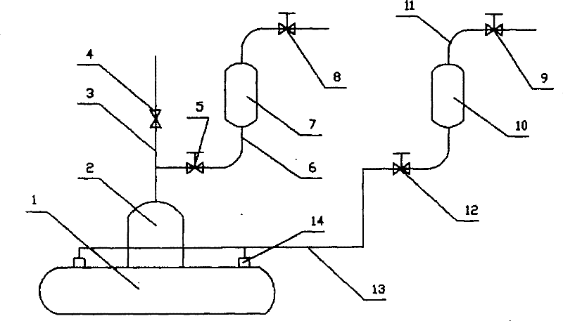
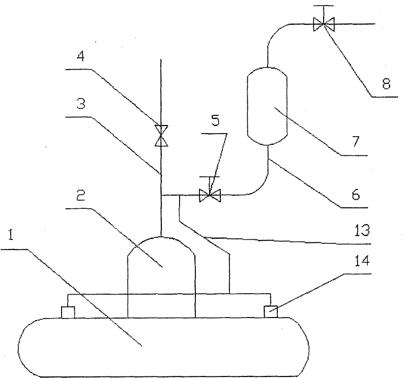
[0010] see figure 1 and figure 2 , the thermal deaerator of the present invention is based on the existing thermal deaerator, and one or more exhaust ports 14 are set at the edge of the top of the water tank 1, and the water tank contains Oxygen gas is discharged, thereby improving the oxygen removal rate.

[0011] The thermal deaerator provided by the present invention includes a thermal deaerator body composed of a degassing tower 2 and a water tank 1. The water tank is installed at the bottom of the degassing tower and communicated with the degassing tower. The degassing tower is provided with a steam inlet One or more water tank exhaust ports 14 are arranged on the peripheral position of the top of the water tank, and the one or more water tank exhaust ports are connected to a water tank exhaust pipe 13 .

[0012] Described water tank exhaust pipe can be connected to the exhaust pipeline that the top of described degassing tower is provided with (as figure 2 shown). ...


PUM


Abstract

The invention relates to a method for improving the deoxygenating effect of a thermal deoxygenator. One or a plurality of cistern exhaust openings are arranged in the peripheral position at a cistern top of the thermal deoxygenator, the oxygen accumulated at the cistern top is discharged through the cistern exhaust openings, and the oxygen is discharged in a continuous mode or intermittent mode. The invention also relates to the thermal deoxygenator using the method, which comprises a thermal deoxygenator body comprising a degassing tower and a cistern, wherein the cistern is installed at thebottom of the degassing tower and is communicated with the degassing tower; the degassing tower is provided with a gas inlet pipe and a water inlet pipe; and one or a plurality of cistern exhaust openings are arranged in the peripheral position at the cistern top and are connected with a cistern exhaust pipe. The invention can remove the oxygen accumulated at the upper part of the cistern in timeto prevent the oxygen from dissolving into water again, is favorable for lowering the oxygen content in the discharged water, improves the deoxygenating effect of the deoxygenator, and is mainly usedfor boiler systems and especially large boiler systems.

Description

technical field [0001] The invention relates to a method for improving the oxygen removal effect of a thermal deaerator, and also relates to a thermal deaerator adopting the method, which can be mainly used for thermal deaeration of boiler feed water, especially for large boiler feed water. Background technique [0002] China No. 200420120557.0 utility model patent application discloses a low-level thermal deaerator, which includes a deaerator body and a water pump. The deaerator body is mainly composed of a deaeration tower and a water tank. There are steam inlet pipe, water inlet pipe and steam exhaust pipe. The water pump is located under the deaerator body and connected with the water tank. The steam exhaust pipe is provided with an automatic control valve. This deaerator eliminates a series of defects such as large civil construction investment, difficult hoisting, long construction period, and certain cavitation to the water pump of common high-level thermal deaerators...

Claims


Application Information

Patent Timeline
Patent Type & Authority Patents(China)
IPC IPC(8): B01D19/00C02F1/20
Inventor 李树生
Owner 李树生
Learn More