Liquefied soil foundation quake-proof road-bridge transition section structure of ballastless track of high-speed railway

A ballastless track and high-speed railway technology, applied in the direction of tracks, roads, bridges, etc., can solve the problems affecting the high-speed, safe and comfortable running state of the train, the increase of the interaction force between the train and the line structure, and the inconsistent settlement of the embankment and the abutment, etc. problems, to achieve the effect of reducing poor mechanical properties, comfortable driving goals, and smooth driving goals

Inactive Publication Date: 2010-04-07
SOUTHWEST JIAOTONG UNIV +1
View PDF0 Cites 37 Cited by
  • Summary
  • Abstract
  • Description
  • Claims
  • Application Information

AI Technical Summary

Problems solved by technology

During an earthquake, due to the uncoordinated deformation caused by the large difference in stiffness between the embankment and the abutment, it is easy to cause inconsistencies in the settlement of the embankment and the abutment, resulting in the bending of the rail surface
When the train passes at high speed, it will cause the increase of the interaction force between the train and the line structure, affect the stability of the line structure, and affect the high-speed, safe and comfortable running state of the train

Method used


Image

  • Liquefied soil foundation quake-proof road-bridge transition section structure of ballastless track of high-speed railway
  • Liquefied soil foundation quake-proof road-bridge transition section structure of ballastless track of high-speed railway
  • Liquefied soil foundation quake-proof road-bridge transition section structure of ballastless track of high-speed railway

Examples


Embodiment Construction

[0017] The present invention will be further described below in conjunction with the accompanying drawings and embodiments.

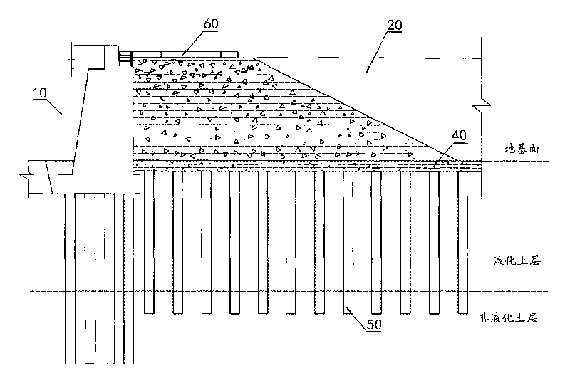
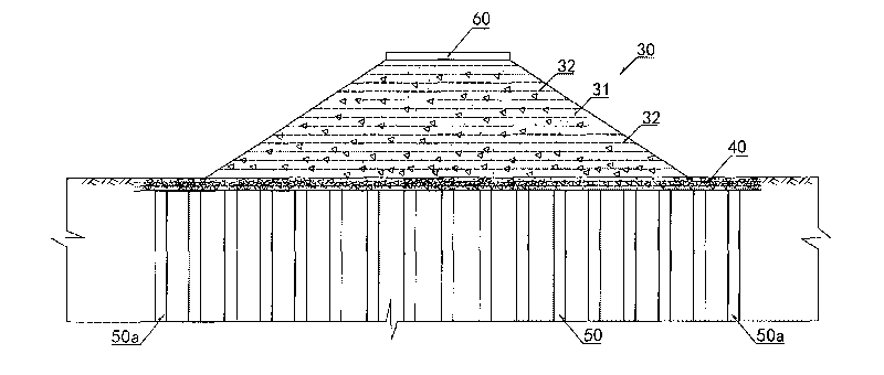
[0018] refer to figure 1 and figure 2 , the structure of the seismic road-bridge transition section of the liquefied soil foundation of the ballastless track of the high-speed railway, including a concrete abutment 10 and an earthen roadbed 20, and between the concrete abutment 10 and the earthen roadbed 20, there is a wedge-shaped longitudinal section and a regular trapezoidal cross-section. Reinforced graded crushed stone transition section 30. Rows of reinforcement piles 50 are arranged vertically and horizontally in the liquefied soil foundation below, and the pile ends of each reinforcement pile 50 go through the liquefied soil layer of the foundation and go deep into the non-liquefied soil layer. Between the foundation surface and the top of the reinforced pile 50, a cement-graded crushed stone reinforced cushion 40 is laid. refer to figure 1...


PUM


Abstract

The invention discloses a liquefied soil foundation quake-proof road-bridge transition section structure of a ballastless track of a high-speed railway, and aims to improve the stability and the integrity of the roadbed at the transition section and meet the quake-proof design requirements of lines. The structure comprises a concrete bridge abutment (10) and a soil roadbed (20). A reinforced grading gravel transition section (30) is arranged between the concrete bridge abutment (10) and the soil roadbed (20), wherein the longitudinal section of the transition section is wedge-shaped and the transverse section of the transition section is right trapezoidal. Rows of reinforcing piles (50) are arranged in the liquefied soil foundation at intervals along the longitudinal and transverse directions under the transition section (30). The pile ends of the reinforcing piles (50) pass through the liquefied soil layer of the foundation and enter a non-liquefied soil layer. A cement grading gravel reinforced cushion layer (40) is paved between the foundation surface and the pile top of the reinforcing pile (50). A reinforced concrete lap plate (60) is arranged on the top surface of the reinforced grading gravel transition section (30). One end of the reinforced concrete lap plate (60) is simply supported or fixedly supported on the concrete bridge abutment (10), while the other end is placed on the soil roadbed (20).

Description

technical field [0001] The invention relates to a high-speed railway ballastless track road foundation, in particular to an anti-seismic road-bridge transition section structure used for a high-speed railway ballastless track liquefied soil foundation. Background technique [0002] A high-speed railway line is composed of a large number of structures (such as bridges, tunnels, roadbeds, etc.) and tracks with different characteristics and characteristics. They interact and influence each other to form a smooth strip line. Due to the differences in material, rigidity, strength and deformation of the structures that make up the line, it will inevitably cause track irregularities. Among them, the embankment at the junction with the bridge structure has always been a weak link of the railway subgrade. During an earthquake, due to the incongruous deformation caused by the large difference in stiffness between the embankment and the abutment, it is easy to cause inconsistent settl...

Claims


Application Information

Patent Timeline
Patent Type & Authority Applications(China)
IPC IPC(8): E01B2/00E01D19/02
Inventor 蒋关鲁张俊兵杭红星肖金良张宇宁吴丽君
Owner SOUTHWEST JIAOTONG UNIV
Why Eureka
Try Eureka