Axial and radial flowing compressor with axial chute processor casing structure

A technology for processing casings and compressors, which is applied in the direction of machines/engines, mechanical equipment, liquid fuel engines, etc., and can solve problems such as narrow compressor stable flow range, performance deterioration, and narrow stable operating range of axial-flow compressors. Achieve the effects of improving the stable operating range, uniform flow, improving efficiency and stable range

Inactive Publication Date: 2010-04-07
TSINGHUA UNIV
View PDF0 Cites 18 Cited by
  • Summary
  • Abstract
  • Description
  • Claims
  • Application Information

AI Technical Summary

Problems solved by technology

The stable operating range of the axial-flow compressor is narrow, and the inlet conditions of the radial-flow compressor are affected by the outlet airflow of the axial-flow stage and the performance deteriorates, resulting in a narrow stable flow range of the entire compressor

Method used


Image

  • Axial and radial flowing compressor with axial chute processor casing structure
  • Axial and radial flowing compressor with axial chute processor casing structure
  • Axial and radial flowing compressor with axial chute processor casing structure

Examples


Embodiment Construction

[0021] The working principle, working process and specific structure of the present invention will be further described below in conjunction with the accompanying drawings.

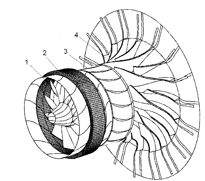
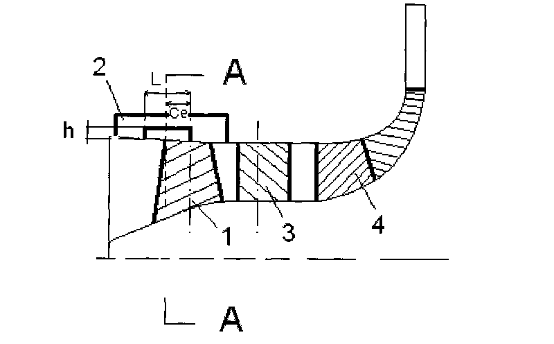
[0022] figure 1 is a three-dimensional structural view of the present invention. figure 2 is the meridian view of the axial flow compressor.

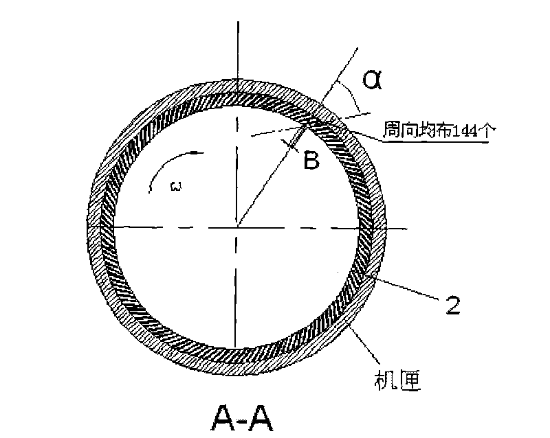
[0023] Such as figure 1 , 2 As shown, the axial-radial compressor mainly includes an axial-stage rotor 1 , an axial-flow stator 3 , and a radial-stage compressor 4 . The axial-flow stage rotor, stator, and radial-flow stage compressor are sequentially connected coaxially and in series. On the casing of the axial-flow stage rotor of the axial radial-flow compressor, a casing processing structure with an axial chute is adopted to widen the stable flow range of the whole-stage compressor. Since the stable flow range of the axial flow stage is narrower than that of the centrifugal stage, the stable flow range of the radial flow compressor is not wide. The resear...


PUM


Abstract

The invention relates to an axial and radial flowing compressor with an axial chute processor casing structure, belonging to the technical field of impeller machinery; the axial and radial flowing compressor comprises an axial flowing rotor, an axial flowing stator and a radial-flowing compressor which are coaxially connected sequentially; axial chutes which are circumferentially distributed uniformly are processed on a casing wall surface of the axial flowing rotor of the axial and radial flowing compressor, the axial chute is radially inclined with 30-60 degrees along the rotating direction of the rotor. In the axial and radial flowing compressor with the axial chute processor casing structure, the low-energy tip clearance vortex of axial-flowing grade blade tip can be effectively controlled under the pumping action of the axial chute processor casing on the axial flowing rotor, flow separation is inhibited under a low flow-rate condition, the entrance condition of the radial flowing compressor is improved, so as to improve surge-to-stall margin of the axial and radial flowing compressor greatly on the premise of ensuring the little change of pressure ratio and efficiency.

Description

technical field [0001] The present invention relates to an axial radial flow compressor, in particular to an axial radial flow compressor with an axial chute processing case structure, which can be used as a compressor for various purposes such as superchargers for vehicles, ships, and aviation, and The utility model relates to an axial flow compressor of a turboshaft engine for various purposes such as aviation, industry, power generation, etc., and belongs to the technical field of impeller machinery. Background technique [0002] High-level turbocharging is to increase engine power per liter, reduce engine displacement and reduce CO 2 efficient way to discharge. The development of turbochargers with high pressure ratio, high efficiency, high reliability and large flow range is of great significance in both military and civilian fields. [0003] In the characteristics of the compressor, due to the interaction between the shock wave and the boundary layer and the leakage ...

Claims


Application Information

Patent Timeline
Patent Type & Authority Applications(China)
IPC IPC(8): F04D25/16F04D29/26
CPCF04D29/685F04D29/526
Inventor 郑新前杨名洋张扬军
Owner TSINGHUA UNIV
Why Eureka
Try Eureka