
Laser following control method and system in laser processing system

A technology of laser processing and control methods, applied in laser welding equipment, metal processing equipment, manufacturing tools, etc., can solve the problems of increasing manufacturing costs, reducing the overall efficiency of the laser cutting system, unqualified, etc., and achieve the effect of improving the overall efficiency

Active Publication Date: 2013-04-17
HANS CNC SCI & TECH
View PDF0 Cites 0 Cited by
  • Summary
  • Abstract
  • Description
  • Claims
  • Application Information

AI Technical Summary

Problems solved by technology

Moreover, the existing control systems implemented by PLC are all open-loop systems, which directly use the pulses sent by the control PLC to the servo motor to control the corresponding position, which is prone to system deviation, resulting in the processed finished product being either unqualified or unqualified. Either requires rework, which increases manufacturing costs and reduces the overall efficacy of the laser cutting system

Method used


Image

  • Laser following control method and system in laser processing system
  • Laser following control method and system in laser processing system

Examples


Embodiment Construction

[0013] Further details will be given below in conjunction with the preferred embodiments shown in the accompanying drawings.

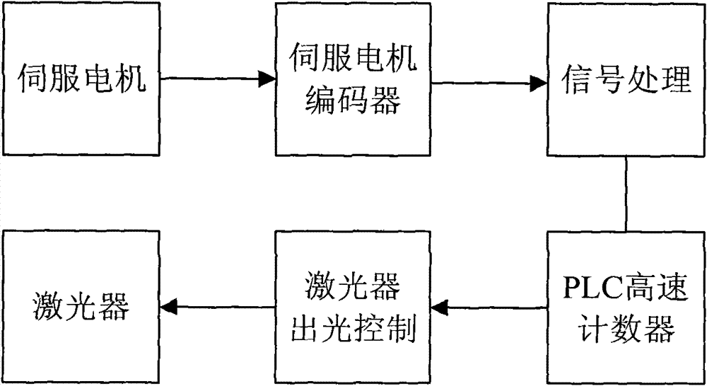
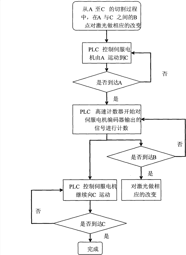
[0014] see figure 1 , the control method of the laser cutting system of the present invention is that a servo motor encoder is arranged on the servo motor, and the output signal of the servo motor encoder is frequency-divided, so that the frequency of the output pulse signal is within the allowable range of the PLC high-speed counter, Then the differential signal output by the servo motor encoder is processed by the external signal conversion circuit to make it meet the input conditions of the PLC. Then, the running distance of the servo motor is counted through the high-speed counter of the PLC, and the "distance" of the trajectory and position of the servo motor relative to the starting point can be known through the value in the counter. When the "distance" is known, the energy, on, off, etc. of the laser can be accurately and timely controlled at ...


PUM


Abstract

The invention relates to a laser following control method and a system thereof in a laser processing system, wherein the laser processing system comprises a servo motor and a laser. A PLC is arranged in the laser processing system and used for outputting corresponding pulse control signals to the servo motor so as to determine a walking track of a laser head and outputting corresponding control signals of energy change, laser open and off to the laser to realize laser following control; and an encoder is also arranged in the laser processing system to detect the position of the servo motor, detecting output signals of the encoder are processed and transformed into pulse signals which can be accepted by a counter in the PLC, and then the PLC knows the distance of the motion track and position of the servo motor relative to a starting point and outputs corresponding control signals of energy change and laser open and off to the laser according to a value of the counter in the current scanning period in time, thus realizing real-time closed loop control of the laser following and improving the overall effectiveness of the laser processing system.

Description

technical field [0001] The invention relates to a laser processing process, in particular to a laser follow-up control method during laser processing. Background technique [0002] In the current laser processing system, such as laser cutting system, it usually includes: actuators such as servo motors and lasers, and their control is realized by PLC, that is, the servo motor is controlled by the PLC program through the servo driver to determine the laser head. Walking trajectory, and control the opening, closing and energy change of the laser emitted by the laser to determine the cutting shape required for processing. Since the execution of the PLC program will lag behind the input of one scan cycle, that is, when the servo motor is in continuous motion, when the laser needs to perform energy changes at a certain position, turn on the laser or turn off the laser, the PLC will receive the instruction to There will be a delay of one scan cycle to execute the output. The exis...

Claims


Application Information

Patent Timeline
Patent Type & Authority Patents(China)
IPC IPC(8): B23K26/00
Inventor 高云峰陈国栋严超翟学涛雷群
Owner HANS CNC SCI & TECH
Learn More