Full-automatic accessory screwdriver

An electric screwdriver and screwdriver technology, applied in screwdrivers, motor tools, wrench, etc., can solve the problems of high cost, low work efficiency, and stuck nails

Inactive Publication Date: 2010-04-14
STATE GRID CORP OF CHINA +1
View PDF2 Cites 9 Cited by
  • Summary
  • Abstract
  • Description
  • Claims
  • Application Information

AI Technical Summary

Problems solved by technology

Although the above can realize the automatic conveying of screws, there are still some deficiencies: on the one hand, when the screws are conveyed from the launch device to the screwdriver, there will always be a nail stuck ph

Method used


Image

  • Full-automatic accessory screwdriver
  • Full-automatic accessory screwdriver
  • Full-automatic accessory screwdriver

Examples


Embodiment 1

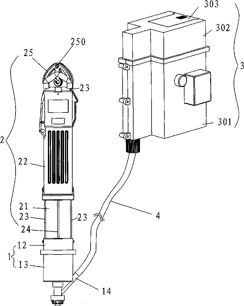
[0037] See Figure 1-10 , a fully automatic batching screwdriver, comprising an electric screwdriver 2, a coordinator 1, a conveying pipe 4 for conveying screws and a screw sending device 3, the feeding port of the conveying pipe 4 is connected to the discharge port of the screw sending device 3, and the conveying pipe 4 The outlet of the feed port is connected to the feed port 14 of the coordinator 2, and the coordinator 1 is connected to the bottom of the electric screwdriver 2.

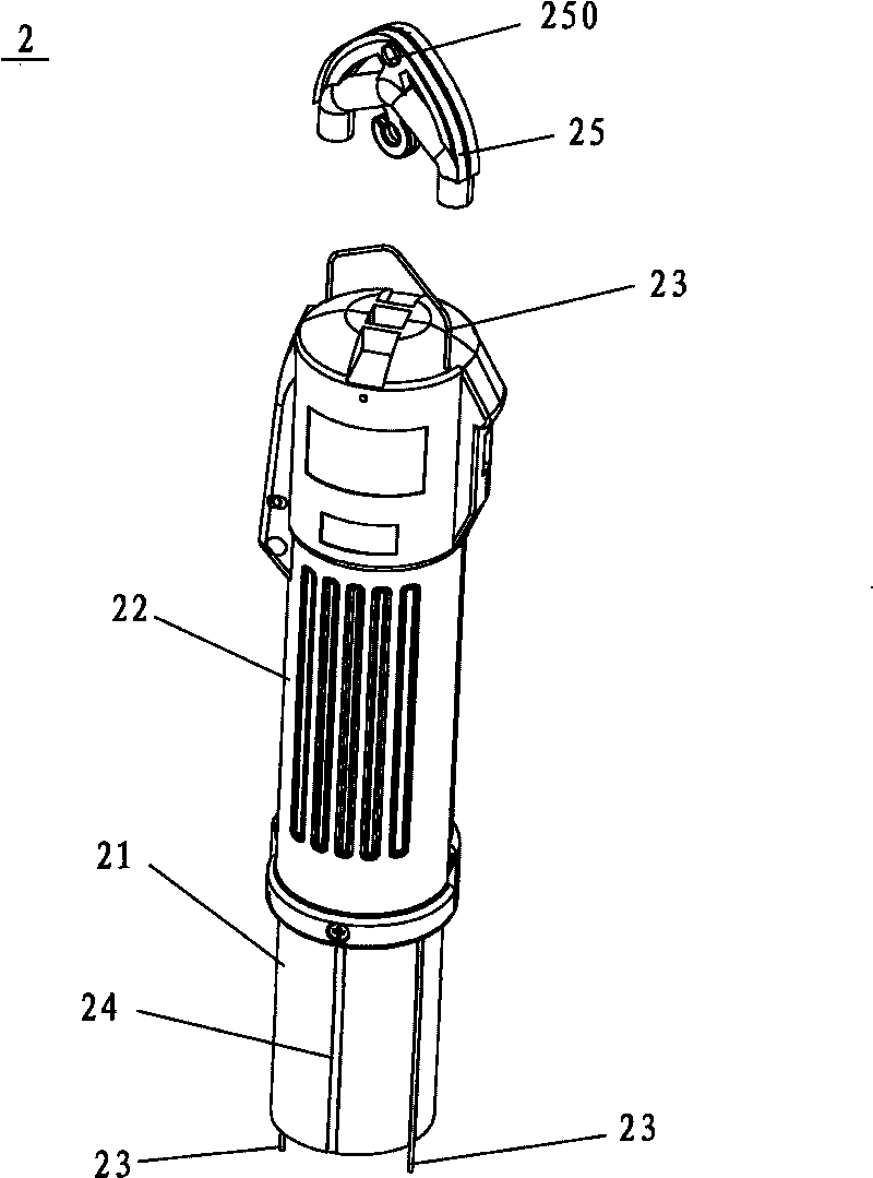
[0038]Electric screwdriver 2 is made up of screwdriver shell 22 and screwdriver body 21, is provided with at least one U-shaped pull bar 23 between screwdriver shell 22 and screwdriver body 21, and the U-shaped end of pull bar 23 is exposed on screwdriver shell 22 tops, and the two pins of pull bar 23 The end passes through the top of the screwdriver shell, extends along the outside of the screwdriver body to the bottom of the electric screwdriver, and is symmetrically fixed on the bayonet 12 of th...

Embodiment 2

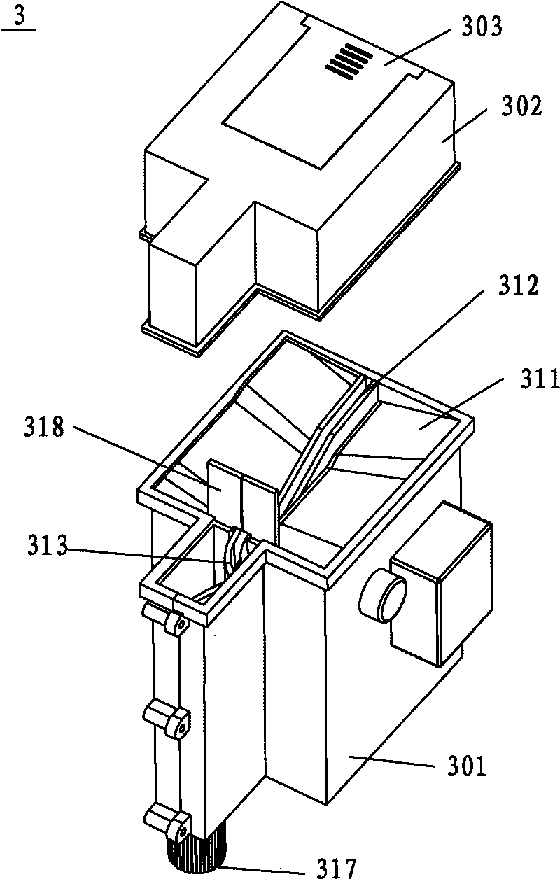
[0040] The structure is the same as in Example 1, except that the angle between the two material receiving plates 311 and the vibrating material tank 312 is 40 degrees, and the two material receiving plates are inclined downward toward the baffle plate, and form an angle of 60 degrees with the horizontal plane; The side of the vibrating trough 312 near the baffle plate 318 is inclined downwards, and forms an angle of 20 degrees with the horizontal plane; the discharge end of the deceleration bend 313 is inclined downwards, and forms an angle of 35 degrees with the horizontal plane; the guide tube The discharge end of 314 is biased towards the baffle plate 318, and forms an included angle of 45 degrees with the vertical direction.

Embodiment 3

[0042] The structure is the same as in Embodiment 1, except that the angle between the two material receiving plates 311 and the vibrating material tank 312 is 50 degrees, and the two material receiving plates are inclined downward toward the baffle plate, and form an angle of 5 degrees with the horizontal plane. The side of the vibrating trough 312 near the baffle plate 318 is inclined downwards, and forms an angle of 15 degrees with the horizontal plane; the discharge end of the deceleration bend 313 is inclined downwards, and forms an angle of 25 degrees with the horizontal plane; the guide tube The discharge end of 314 is biased towards the baffle plate 318, and forms an included angle of 30 degrees with the vertical direction.


PUM


Abstract

The invention relates to the technical field of screwdrivers, in particular to a full-automatic accessory screwdriver which comprises an electric screwdriver, a coordination machine, a delivery pipe for delivering screws and a screw transmitting device, wherein the screw transmitting device is provided with a decelerating bent groove and a guide tube. In the invention, mechanical motility is mainly utilized, full automation during the delivering process is realized by a tilting structure and the self gravity of the screw, not only the time for manually grabbing the screw and the use cost are saved, but also the screws entering a material bearing space can be delivered to the entrance for the screw completely, and especially, nail clamping phenomenon is avoided during the continuous delivery process; and the screw transmitting device is internally provided with an electronic automatic monitoring energy-saving device, and when the delivery pipe for delivering the screws is filled with screws to the monitoring position, the device can automatically cut off the power, and then restore to work in the set time, thus saving energy source.

Description

technical field [0001] The invention relates to the technical field of screwdrivers, in particular to a fully automatic batching screwdriver. Background technique [0002] When using an electric screwdriver to screw in a screw into the screw hole, it is usually necessary to manually pick out the screw and manually position the screw on the screw hole before screwing the screw into the screw hole. The operation speed is slow and the work efficiency is low. . [0003] In order to improve work efficiency, people have done a lot of research, and have developed an invention that does not need to pick out the screw automatically by hand, as the Chinese patent, the application number is 200520072590.5 discloses a kind of automatic nail feeding electric screwdriver, including electric screwdriver. Screwdriver, the head of the electric screwdriver is equipped with an automatic nail-feeding electric locking mechanism. The main body of the mechanism is connected by a straight line cha...

Claims


Application Information

Patent Timeline
IPC IPC(8): B25B21/00B25B23/04
Inventor 徐荣富
Owner STATE GRID CORP OF CHINA
Why Eureka
Try Eureka