Full-automatic accessory screwdriver
An electric screwdriver and screwdriver technology, applied in screwdrivers, motor tools, wrench, etc., can solve the problems of high cost, stuck nails, and low work efficiency
- Summary
- Abstract
- Description
- Claims
- Application Information
AI Technical Summary
Problems solved by technology
Method used
Image
Examples
Embodiment 1
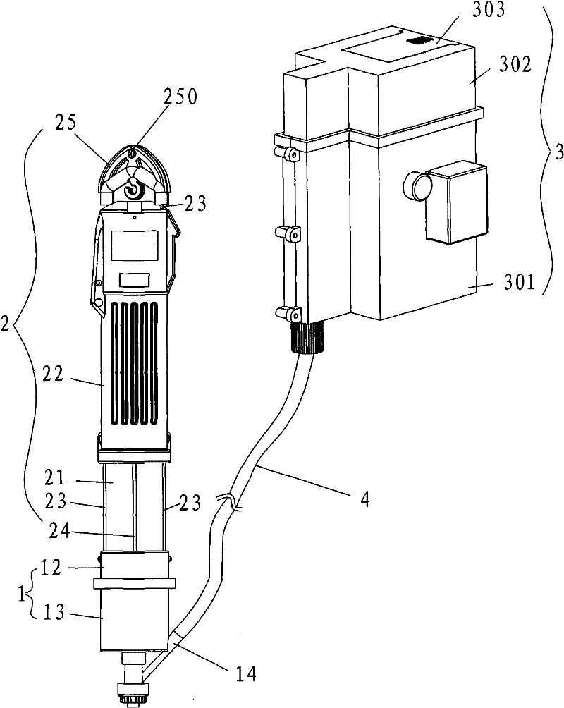
[0038] See Figure 1-10 , a fully automatic batching screwdriver, comprising an electric screwdriver 2, a coordinator 1, a conveying pipe 4 for conveying screws and a screw sending device 3, the feeding port of the conveying pipe 4 is connected to the discharge port of the screw sending device 3, and the conveying pipe 4 The outlet of the feed port is connected to the feed port 14 of the coordinator 2, and the coordinator 1 is connected to the bottom of the electric screwdriver 2.
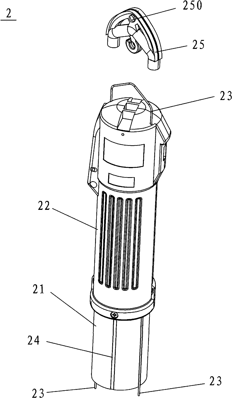
[0039]Electric screwdriver 2 is made up of screwdriver shell 22 and screwdriver body 21, is provided with at least one U-shaped pull bar 23 between screwdriver shell 22 and screwdriver body 21, and the U-shaped end of pull bar 23 is exposed on screwdriver shell 22 tops, and the two pins of pull bar 23 The end passes through the top of the screwdriver shell, extends along the outside of the screwdriver body to the bottom of the electric screwdriver, and is symmetrically fixed on the bayonet 12 of th...
Embodiment 2
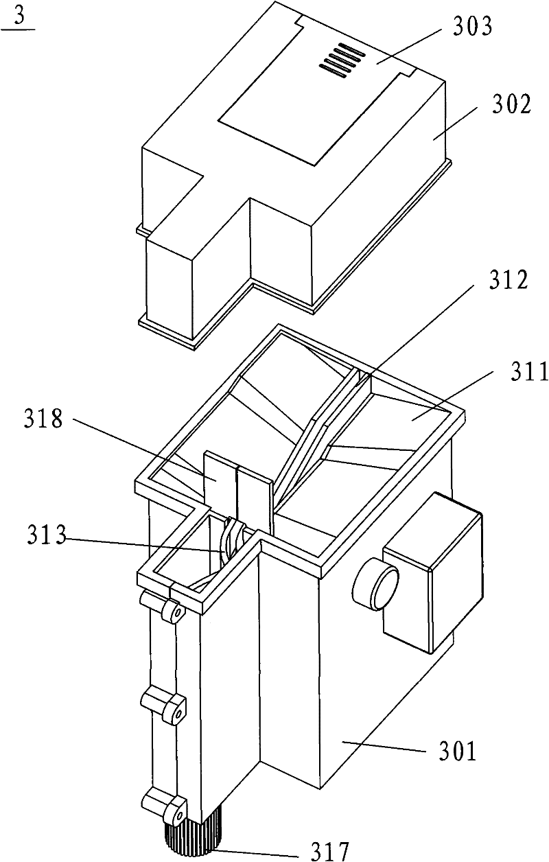
[0041] The structure is the same as in Example 1, except that the angle between the two material receiving plates 311 and the vibrating material tank 312 is 40 degrees, and the two material receiving plates are inclined downward toward the baffle plate, and form an angle of 60 degrees with the horizontal plane; The side of the vibrating trough 312 near the baffle plate 318 is inclined downwards, and forms an angle of 20 degrees with the horizontal plane; the discharge end of the deceleration bend 313 is inclined downwards, and forms an angle of 35 degrees with the horizontal plane; the guide tube The discharge end of 314 is biased towards the baffle plate 318, and forms an included angle of 45 degrees with the vertical direction.
Embodiment 3
[0043] The structure is the same as in Embodiment 1, except that the angle between the two material receiving plates 311 and the vibrating material tank 312 is 50 degrees, and the two material receiving plates are inclined downward toward the baffle plate, and form an angle of 5 degrees with the horizontal plane. The side of the vibrating trough 312 near the baffle plate 318 is inclined downwards, and forms an angle of 15 degrees with the horizontal plane; the discharge end of the deceleration bend 313 is inclined downwards, and forms an angle of 25 degrees with the horizontal plane; the guide tube The discharge end of 314 is biased towards the baffle plate 318, and forms an included angle of 30 degrees with the vertical direction.
PUM
 Abstract
Description
Claims
Application Information
 - R&D
- Intellectual Property
- Life Sciences
- Materials
- Tech Scout
- Unparalleled Data Quality
- Higher Quality Content
- 60% Fewer Hallucinations
Browse by: Latest US Patents, China's latest patents, Technical Efficacy Thesaurus, Application Domain, Technology Topic, Popular Technical Reports.
© 2025 PatSnap. All rights reserved.Legal|Privacy policy|Modern Slavery Act Transparency Statement|Sitemap|About US| Contact US: help@patsnap.com


