Solar direct current (DC) lamp circuit

A solar energy and circuit technology, used in electric light sources, electrical components, lighting devices, etc., can solve the problems of short switching life, hidden safety hazards, and large losses, and achieve the effects of low withstand voltage requirements, high electrical conversion efficiency, and small size.

Inactive Publication Date: 2010-04-14
SICHUAN QUANCHENG ENERGY SAVING TECH
View PDF0 Cites 2 Cited by
  • Summary
  • Abstract
  • Description
  • Claims
  • Application Information

AI Technical Summary

Problems solved by technology

[0008] The purpose of the present invention is to provide a solar DC lamp circuit, which solves the problems of large loss, low efficiency, short switch life and potential safety hazards in the existing DC lamp circuit structure

Method used


Image

  • Solar direct current (DC) lamp circuit
  • Solar direct current (DC) lamp circuit
  • Solar direct current (DC) lamp circuit

Examples


Embodiment Construction

[0023] The present invention will be described in detail below in conjunction with the accompanying drawings and with the best embodiment.

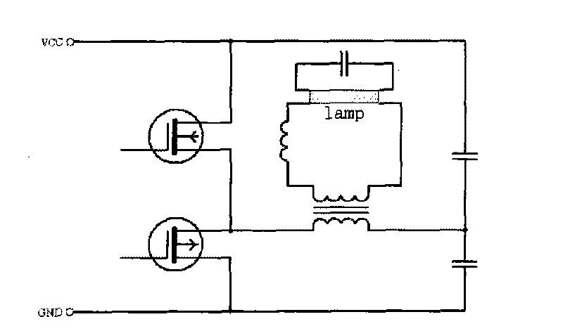
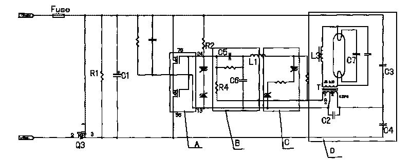
[0024] refer to figure 2 , image 3 , solar DC lamp circuit, including:

[0025] Solar drive circuit A;

[0026] The circuit drive network B is used for the pulse generating device to drive pulse generation; the circuit drive network B is connected to the output of the solar drive circuit A;

[0027] Voltage divider clamping circuit C, the voltage divider resistor forms negative feedback to the driving circuit, the voltage regulator tube divides the driving signal and clamps the peak value, and suppresses the driving voltage at the moment of startup and high voltage input; the voltage dividing clamping circuit C and the circuit drive network B parallel;

[0028] The circuit structure D of the lamp tube is composed of a lamp tube, a starting capacitor and a transformer T, and the circuit structure D of the lamp tube is connected in pa...


PUM


Abstract

The invention relates to a solar direct current (DC) lamp circuit, relating to a circuit structure and comprising a solar driving circuit (A), a circuit-driving network (B), a voltage-dividing clamping circuit (C) and a lamp circuit structure (D). The circuit-driving network (B) is used for a pulse generator to generate pulses; in the voltage-dividing clamping circuit (C), a divider resistor forms negative feedback to the driving circuit (A), a stabilivolt tube divides the voltage of a driving signal, clamps the peaks of the driving signal and restrains driving voltages in a starting moment and a high-voltage input moment; and the lamp circuit structure (D) comprises a lamp, a start capacitor and a transformer (T) and is connected in parallel with the voltage-dividing clamping circuit (C). The invention solves the problems of the traditional DC lamp circuit structure, such as great loss, low efficiency, short service life of switches and security risk.

Description

technical field [0001] The invention relates to a circuit structure, in particular to a circuit structure for power supply of a solar DC lamp. Background technique [0002] There are mainly two types of DC lamp circuit structures currently used, one is the ROYER push-pull circuit, and the other is the single-tube flyback circuit. [0003] Due to the low efficiency of the flyback circuit (generally about 50%), the output AC waveform is asymmetrical up and down, and the rectification effect of the lamp is relatively heavy. In addition, the circuit is very damaged to the lamp, and the switching times are at most about 1000 times, so the practical application is rarely used in . [0004] Such as figure 1 As shown, the traditional Royer line is easy to calculate the frequency and start-up conditions, generally in L 初级线圈× 2 The initial frequency is calculated with the resonant capacitor, which is widely used in low-voltage power supply. Today’s current market, including the exi...

Claims


Application Information

Patent Timeline
Patent Type & Authority Applications(China)
IPC IPC(8): H05B41/14
Inventor 邓金和
Owner SICHUAN QUANCHENG ENERGY SAVING TECH
Why Eureka
Try Eureka