
Hybrid magnetic bearing switched reluctance motor and control method thereof

A switched reluctance motor and hybrid magnetic bearing technology, which is applied in the direction of AC motor control, control system, and mechanical energy control, can solve problems such as limited starting performance, difficulty in precise control of high-speed suspension, and large torque ripple.

Active Publication Date: 2017-07-14
南京埃克锐特机电科技有限公司
View PDF3 Cites 11 Cited by
  • Summary
  • Abstract
  • Description
  • Claims
  • Application Information

AI Technical Summary

Problems solved by technology

[0005] However, since the magnetic bearing and the switched reluctance motor share the same stator, there is a strong magnetic coupling between the two-phase armature winding and the four suspension windings, and the mathematical model of the suspension force is complex; in addition, the four suspension windings are equivalent to the traditional 8 / 6 The other two phases of the pole switched reluctance motor, and the direction of the generated torque is always opposite, the torque ripple is large, which limits the starting performance. The starting ability of this motor is similar to that of the traditional two-phase motor, and there is a starting dead zone; limited by its structure , the motor cannot achieve decoupling control of torque and suspension force, and it is difficult to accurately control high-speed suspension

Method used


Image

  • Hybrid magnetic bearing switched reluctance motor and control method thereof
  • Hybrid magnetic bearing switched reluctance motor and control method thereof
  • Hybrid magnetic bearing switched reluctance motor and control method thereof

Examples


Embodiment Construction

[0045] The technical scheme of a hybrid magnetic bearing switched reluctance motor and its control method of the present invention will be described in detail below in conjunction with the accompanying drawings:

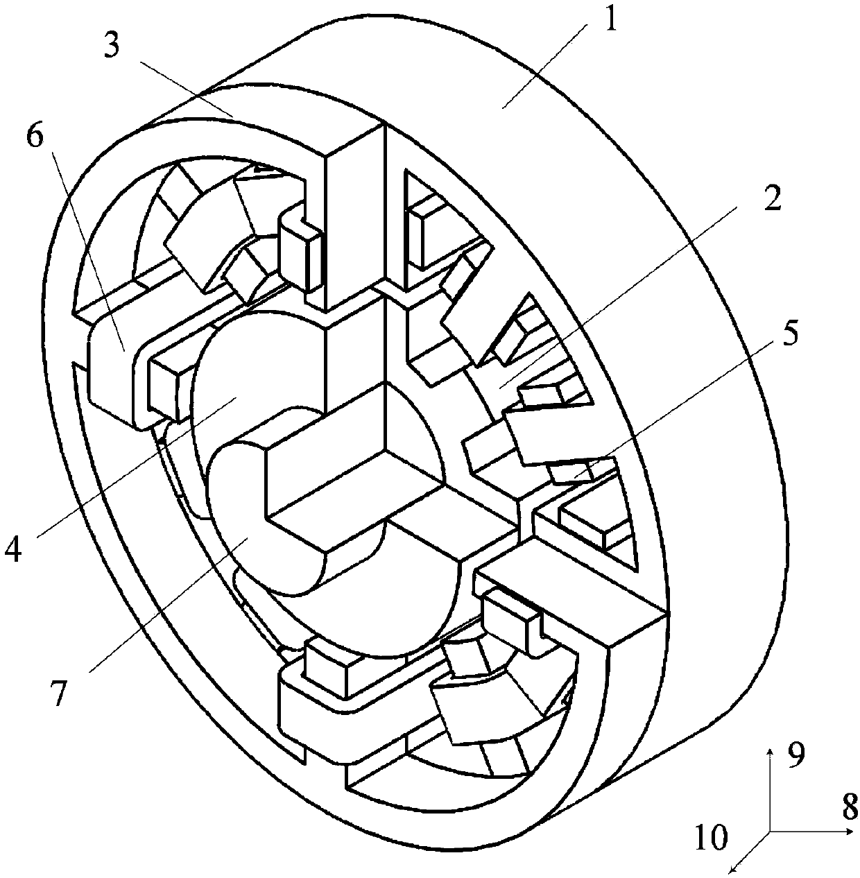
[0046] Such as figure 1 Shown is a three-dimensional schematic diagram of the hybrid magnetic bearing switched reluctance motor, where 1 is the reluctance motor stator, 2 is the reluctance motor rotor, 3 is the magnetic bearing stator, 4 is the magnetic bearing rotor, 5 is the torque coil, 6 is a suspension coil, and 7 is a rotating shaft.

[0047] A hybrid magnetic bearing switched reluctance motor, comprising a reluctance motor stator, a reluctance motor rotor, a magnetic bearing stator, a magnetic bearing rotor, a torque coil, a suspension coil and a rotating shaft;

[0048] The stator of the reluctance motor is closely arranged in series with the stator of the magnetic bearing, the rotor of the reluctance motor is closely arranged in series with the rotor of the...


PUM


Abstract

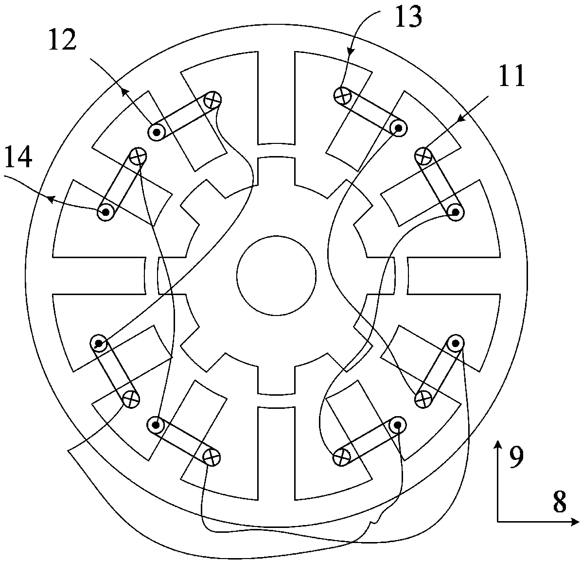
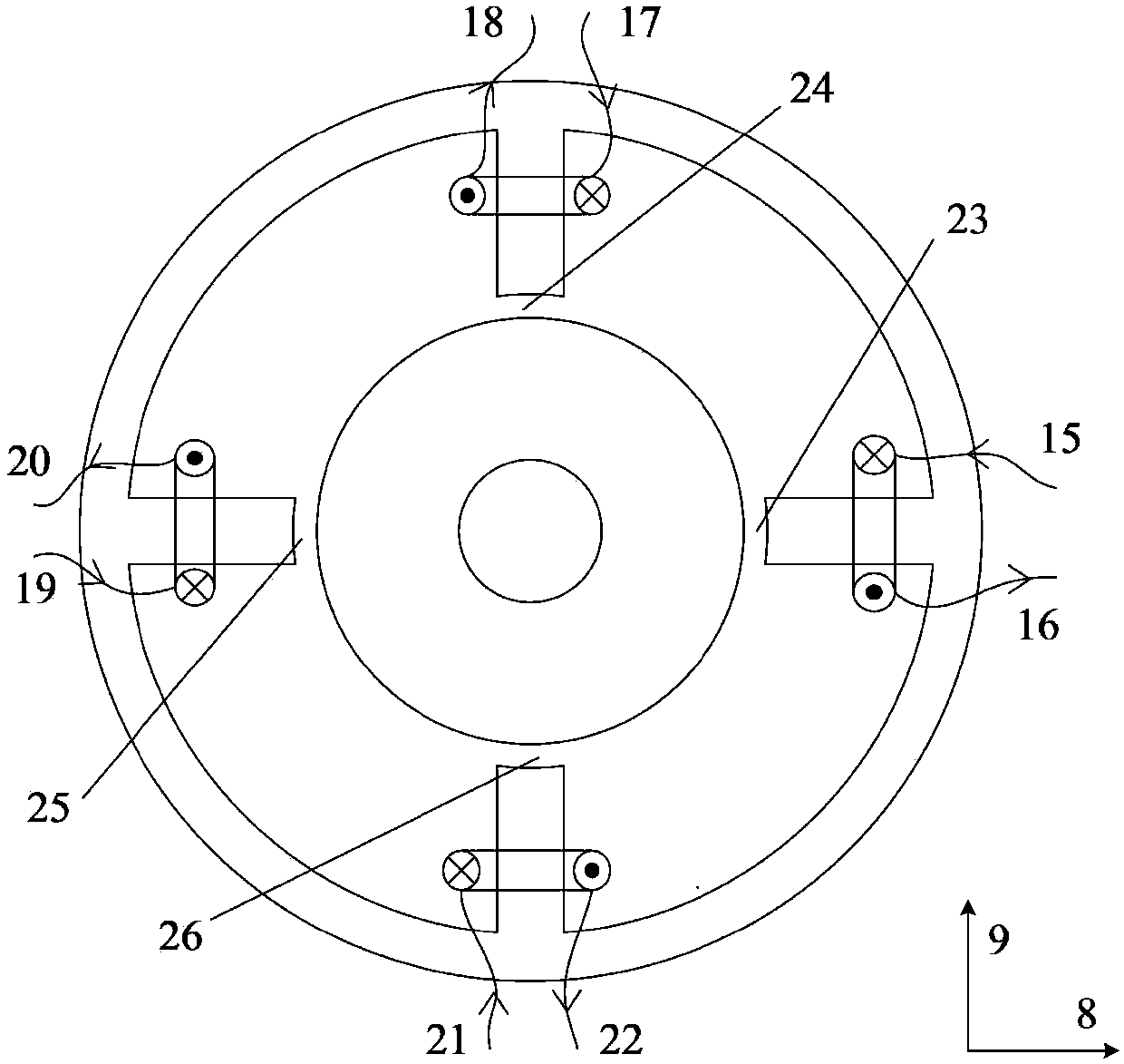
The invention discloses a hybrid magnetic bearing switched reluctance motor and a control method thereof, and belongs to the field of a magnetic suspension motor and control thereof. The motor is formed by connecting and integrating a 12-8-pole switched reluctance motor and a 4-pole magnetic bearing in series, wherein four suspension windings are wound around magnetic bearing stators and four reluctance motor stators which are aligned to the magnetic bearing stators, and are used for generating suspension forces, eight armature windings are wound around the other eight reluctance motor stators and are used for generating torques, during control, the suspension windings employ constant conduction excitation, suspension forces are simultaneously generated in the magnetic bearing and the reluctance motor, eight torque windings are connected to form two phases, excitation conduction is performed in turns, and torques are generated in the reluctance motor. According to the control method of the motor, the currents of the suspension windings are symmetric in each positive and negative half period, a positive torque and a negative torque which are generated are equal, the average torque is zero, and thus, the suspension forces and the average torque are decoupled; moreover, the starting performance of the motor is also improved by the positive torque, and the defect of difficulty in starting of a traditional two-phase motor can be overcome; and the hybrid magnetic bearing switched reluctance motor is simple in structure, and a power system is low in cost and is simple to control.

Description

technical field [0001] The invention relates to a hybrid magnetic bearing switched reluctance motor and a control method thereof, and belongs to the technical field of magnetic levitation switched reluctance motors and their control. Background technique [0002] The bearingless switched reluctance motor is a new type of magnetic levitation motor developed in the 1990s. Since the bearingless switched reluctance motor integrates the functions of rotation and suspension, it can not only effectively solve the problems of loss and heat caused by bearing friction during high-speed operation, but also further exert the high-speed adaptability of the switched reluctance motor, thereby strengthening its Application base in high-speed fields such as aerospace, flywheel energy storage, and ships. [0003] With the continuous deepening of research, people gradually realize that whether the constraints between the effective output areas of torque and suspension force can be solved, whe...

Claims


Application Information

Patent Timeline
IPC IPC(8): H02K7/09H02K29/00H02P25/08H02N15/00
CPCH02K7/09H02K29/00H02N15/00H02P25/08
Inventor 刘泽远蔡骏赵春文
Owner 南京埃克锐特机电科技有限公司
Learn More